


Page 13
NOL Compact Modulating
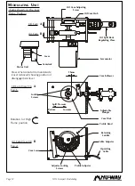
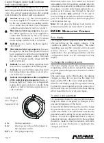
Turning to the air cam (fig. 2 opposite), rotate
the thumbscrews in or out so that they give
a reasonable amount of adjustment in each
direction. Adjust the flexible cable (at either
end if necessary) until the air inlet damper is
fully closed (i.e. until all the slack is taken up
on the cable).
Now adjust the thumbscrews to give a small
opening of the air damper at low flame.
Uncover and replace the photocell. Reset the
sequence control and allow the burner to
start. Immediately the burner starts, switch
the hand/auto selector switch to the hand
position and hold low flame until the
appliance is ready to accept high flame.
During this period, check and adjust the low
flame oil throughput.
Check the flame visually. If the flame is dirty,
adjust the air cam thumbscrews until the
flame becomes clean.
After a suitable delay, inch the camshaft to
the high flame position (i.e. through 180°) by
using the RWF40 control in manual mode
(see page 11). Adjust the air cam profile by
means of the thumbscrews until the air
damper is sufficiently open to give clean
combustion. At this stage it will be found that
all of the thumbscrews between low and high
position will require adjusting so as to avoid
over stressing the cam profile band.
Once this has been done, there should be a fairly
smooth profile between low and high positions.
Ensure that the flame is visually clean throughout
the modulation range at all times.
Check the oil consumption. If this is not correct for
the full burner rating, the oil cam must be adjusted
as follows.
(a)
Inch the burner to low flame and note the
spill pressure.
(b)
To increase the minimum rate, adjust as
shown in fig. 1.
(c)
Adjust the cam to give more eccentricity for
more oil at high flame, and visa versa.
(d)
Return to the minimum setting and
compensate for any changes.
(e)
Inch the burner to high flame and again check
the oil flow.
Continue to repeat (a) to (d) until the high flame
oil rate is correct.
When a satisfactory flame is achieved, again check
the line and spill pressures.
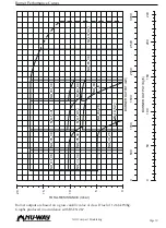
Inch the camshaft back to the low flame
position. The oil consumption rate should
now be between 35 and 50% of the rated
maximum.
Measure the flue gas composition and adjust
the combustion air volume as necessary.
Check the burner performance throughout
the range adjusting the air cam profile as
necessary to give a clean and efficient flame.
When a satisfactory setting has been achieved, lock
the air cam thumbscrews with the grubscrews fitted
in the side face of the cam body. Refit the
Modulating unit access cover.
If the burner control panel is inclusive of Low
Excess low and High Water interlocks and alarms,
test that these function correctly. Ensure that the
boiler feed pump switchgear provided in the panel
is operating satisfactorily.
Adjust the modulating control to the required
pressure/temperature.
Allow the boiler to attain the correct working
pressure/temperature and adjust the on/off and
limit instruments to the desired values.
Return the RWF40 to automatic mode. The plant
is now under the control of the pressure/
temperature controllers for modulation and the on/
off and high limit instruments for control.
Finally check all ancillary controls and equipment
such as damper interlocks etc.
R
OUTINE
M
AINTENANCE
OF
NOL
M
ODULATING
B
URNERS
General
It is vitally important that personnel responsible for
the day to day operation and maintenance of the
plant are instructed by the commissioning engineer
on the basic function of the burner as well as the
need for routine maintenance and daily checking
of burner operations.
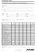
Final adjustments, which will have been made
during the commissioning, must be recorded on
the
Commissioning Sheet
at the back of this manual
and in the appliance
logbook
. A copy of the
commissioning data
must
be sent to the appliance
manufacturer.
The burner should be kept clean inside and out. It
will be more reliable, and if an oil leak occurs it
will be spotted more readily.


