Page 13
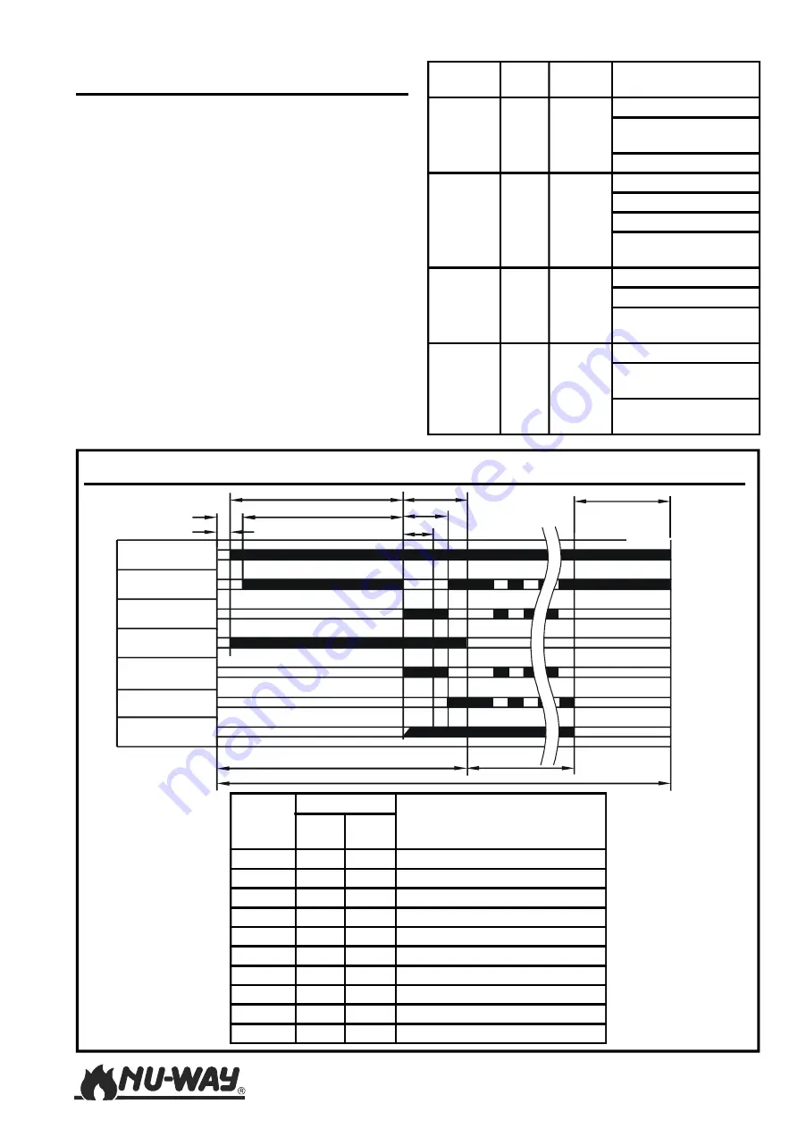
NOL 18-100 HL
PERIOD
TIME (secs)
DESCRIPTION
LAL-
1.25
TMO-
720
t1
2.5
2.5
Start up time for fan motor
t2
5
5
Delay to damper open
t3
22.5
30
Full air pre-purge
t4
11.5
7.5
Delay to 'High flame'
t5
34
30
Pre-ignition
t6
15
7.5
Post Ignition Time
t7
5
5
Safety period
Ts
36.5
40
Total start up time
Tp
15
0
Post purge time
T
51.5
40
Control re-cycle time
COLOUR WHE-
RE
WHAT
REASON
GREEN
End
Does
not start
Incorrect wiring
No voltage at terminal
9
No neutral connection
BLUE
Anyw-
here
Lockout
Stray Light
Photo Cell faulty
Solenoid Leaking
Flame monitoring
circuit broken
YELLOW
(NO
FLAME)
End
Lockout
No ignition
Fuel supply problem
Solenoid valve
defective
YELLOW
(WITH
FLAME)
End
Lockout
Photo cell dirty
Photo cell or circuit
faulty
No voltage at terminal
20
F
LAME
F
AILURE
& S
EQUENCE
C
ONTROL
Various types of control boxes are fitted to the NOL
18-100 High/Low series of burners. This manual
covers the standard models from Satronic and
Landis & Staefa.
The units are designed to provide control and
supervision for atomising oil burners of medium
to large capacity. They are suitable for use on multi-
stage and modulating burners.
For safety reasons, at least one controlled
shutdown must be provided within each 24-hour
period of continuous operation.
Burner Motor
Air Damper Low
Air Damper High
Ignition
Main Oil High
Oil Valves Low
Flame On
Ts
T
Run
T7
t6
Tp
t5
t4
t3
t1
t2
S
EQUENCE
C
ONTROL
T
IMINGS
Summary of Contents for NOL100-38
Page 22: ...NOL 18 100 HL Page 22 NOTES...
Page 23: ...Page 23 NOL 18 100 HL...


