background image

Page 15

XGN Handbook

Press (+) to move the control point to P2,

again making any adjustments to keep the

flame safe and stable.

Follow the above procedure through P3, P4

etc. until position P9, the high fire position,

is obtained.

With the gas butterfly set at 90°, adjust the

governor on the SKP2x valve to give the

required high flame gas flow.

Adjust the air damper position to give the

required combustion analysis. 

Note the air

damper position.

Switch off the burner and restart the

procedure from entering the pass code.

Adjust the value of the air damper at P9 to

that noted above.

Scroll through to the GAS EL display and start

the burner.

At the ignition point P0, adjust the air and

start gas values to give a good light up.

Ensure that the start rate gas flow

does not exceed 30% of the high

flame gas rate as measured at the

Gas Meter  Note the gas and air posi-

tions.

Move to point P1 and adjust the gas butterfly

to give the required low flame gas flow. Adjust

the air damper to give the required

combustion analysis.  

Note the gas and air

positions.

Switch off the burner and restart the

procedure from entering the pass-code.

Adjust the value of the gas and air settings to

those noted at points P0, P1 and P9.

Scroll through to the GAS EL display and start

the burner.

Move to point P2, the firing rate will increase.

Adjust the air damper to give the correct

combustion analysis.

Repeat the above procedure for points P3

through P8, fine tuning the combustion

analysis as required.

When the burner is firing satisfactorily, return

the burner to set point P9.

Two further points 

Bu

 and 

Bo

, which correspond

to the minimum and maximum firing rates can now

be set using the air damper angles that were set at

P1 and P9 respectively.
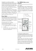
Press keys (1) and (2) together to access the

display point Bu. Wait until the display is

steady. Adjust the value to reflect the air

damper angle at P1.

Press keys (1) and (2) again to access the

display point bo. Wait until the display is

steady. Adjust the value to reflect the air

damper angle at P9.

Finally, press keys (1) and (2) again to enter

the information into memory.

The procedure is now complete.

F

INAL

  A

DJUSTMENTS

Setting the Air Pressure Switch

Switch off the electrical supply to the burner.

Remove the air pressure switch cover.  Fit a

manometer to the pressure switch to check the

accuracy of the dial.
Re-establish the electrical supply.
Enter the pass-code as described on page 13 for a

part commissioning.  The default settings will not

be displayed. Switch on and the burner will purge

then fire at point PO.  Slowly turn the adjusting

dial clockwise until the flame is extinguished; the

burner may  go to lockout. Turn the dial one

division anticlockwise and let the burner restart, if

the burner fails to start, turn the dial another

division anticlockwise.  Repeat the above

procedure at one division per cycle until the

burner operates.  Adjust the dial a further two

divisions anticlockwise.
Switch off the burner, isolate the electrical supply,

fit the cover and remove the manometer.

Setting the Flame Signal

When the burner is operating normally, carefully

turn back the sensitivity control until LED 1 begins

to flicker. Increase the setting again by one or two

increments until both LED’s are lit. If LED 1 does

not flicker even at position 1: Leave potentiometer

at position 1-2. This adjustment should be carried

out when the flame signal current is weakest (at a

cold-start, shortly after flame establishment or af-

ter stabilisation).
The flame signal can be checked by using a

microammeter.
The minimum signal required is 15 µA
The MBC display is designed to give an indication

of the signal, the screen gives a 0 to 4 readout.
See service display screen 18.

Summary of Contents for XGN Series

Page 1: ...Page 1 XGN Handbook HANDBOOK Series XGN fully automatic burners Models XGN450 to XGN3000 Natural Gas...

Page 2: ...es 10 Combustion Chamber Conditions 10 PACKAGING FOR TRANSIT 10 ASSEMBLY 10 INSTALLATION 11 General 11 Fitting to the Appliance 11 Electrical 11 BURNER AIR CONTROLS 11 Air Diffuser 11 Air Pressure Swi...

Page 3: ...r Assembly 19 Air Diffuser and Gas Nozzle 20 Ignition Electrode 20 Replacement of Control Valve SKP2x 20 FAULT FINDING 20 MBC Error Codes 20 Incorrect Rotation of Burner Motor 21 Motor Fan Removal 21...

Page 4: ...XGN Handbook Page 4...

Page 5: ...h a condition should occur during commissioning or subsequent use of this product be it a fault of the burner the appliance or of any instrument machine or service in the proximity of the burner then...

Page 6: ...N1750 38 136 1014 265 255 165 287 104 227 429 583 394 289 2 265 305 XGN2100 34 118 957 265 223 165 287 104 227 385 583 394 269 2 230 305 XGN2350 38 171 1014 265 255 165 287 163 227 429 794 457 289 DN6...

Page 7: ...lame Tube 11 Diffuser Plate 6 Pilot Gas Tube Burner A B C D E F G Nozzle Side Ports Nozzle End Ports XGN450 23 71 96 135 155 146 168 19 8 x 8 0 8 x 4 0 XGN650 23 71 96 135 160 151 168 19 8 x 10 0 8 x...

Page 8: ...el Motor kW rpm Start Current A Full Load Current A Main Fuse A Cable Size mm2 XGN450 23 0 75 2800 8 0 2 0 10 1 0 XGN650 23 0 75 2800 8 0 2 0 10 1 0 XGN1000 25 1 1 2800 9 0 2 7 10 1 0 XGN1150 38 3 0 2...

Page 9: ...LUG HIGH LOW BURNER APPLICABLE TO ALL BURNERS MAKE CONNECTIONS AS APPROPRIATE AUXILLARY CONTACT MOTOR STARTER C ONNECTIONS TO THE 7 4 P IN P LUGS H L B URNER 7 PIN WIELAND B4 S3 T2 T1 N E L1 BURNER RU...

Page 10: ...aintenance To avoid any restriction in gas flow the size of this valve should not be less than that of the gas train FEATURES Flue and Chimney Requirements The flue and chimney must be constructed and...

Page 11: ...perating cycle Air flow failure at any stage after pre purge will result in a lockout failure during pre purge will result in four restarts before a lockout BURNER GAS CONTROLS Gas Nozzle The holes in...

Page 12: ...anual valve for a few seconds then close and secure the gas supply The manometer will detect any gas leakage and will prove that gas is not leaking past the gas train If no drop in pressure is recorde...

Page 13: ...show seven short lines the first flashing and is ready to accept the code The default pass code is 8904236 To enter the first number eight press the plus key eight times or the minus key twice 10 8 2...

Page 14: ...his number nine in this illustration press key nine times or the key once 10 9 1 Again the flashing line will drop to indicate it has been recorded Press key 2 to move to the next number zero the thir...

Page 15: ...2 together to access the display point Bu Wait until the display is steady Adjust the value to reflect the air damper angle at P1 Press keys 1 and 2 again to access the display point bo Wait until th...

Page 16: ...hed off a by controlling instruments of the appliance b manually c by power failure Upon restoration of power the burner will restart automatically and follow the normal sequence THE RWF40 MODULATION...

Page 17: ...ue found to be in error up down buttons At the last screen the PGM button will return the controller to the original operating display Parameter Display Hot Water Steam Proportional band Pb1 10 1 Deri...

Page 18: ...d When in the service mode the display will move to the next screen and finally back to the operating display with each press of the acknowledgement key MBC DISPLAYS Standby Display Operating Display...

Page 19: ...pply to the burner Combustion Air Fan Clean the blades regularly with a stiff brush Access is obtained through the burner top cover Care should be taken to avoid damaging the fan blades Check that the...

Page 20: ...Any modifications to the installation or component settings resulting from actions suggested below may require the re establishment of the various settings During the purges and firing cycles the MBC...

Page 21: ...e gas flow does not exceed 30 of the high flame gas rate as measured at the Gas Meter The gas valve s operate correctly Burner Fails to Establish Main Flame Check The gas butterfly is operating correc...

Page 22: ...SPARE PARTS For spare parts contact Nu way s Parts and Components Division at the address and telephone number listed on the rear cover of this handbook To avoid delays please provide the burner model...

Page 23: ...Page 23 XGN Handbook XGN450 23 XGN650 23...

Page 24: ...XGN Handbook Page 24 XGN1000 25 XGN1150 38...

Page 25: ...I n c h S t d G a s T r a i n G a s H e a d P r e s s u r e C o m b A i r H e a d P r e s s u r e 1 5 I n c h O p t i o n a l G a s T r a i n 2 I n c h S t d G a s T r a i n 2 5 x 2 I n c h O p t i o...

Page 26: ...n c h S t d G a s T r a i n G a s H e a d P r e s s u r e C o m b A i r H e a d P r e s s u r e 2 5 x 2 I n c h O p t i o n a l G a s T r a i n 2 I n c h O p t i o n a l G a s T r a i n 2 5 x 2 I n c...

Page 27: ...2 I n c h S t d G a s T r a i n G a s H e a d P r e s s u r e C o m b A ir H e a d P re s s u re 2 I n c h O p t i o n a l G a s T r a i n 2 5 x 2 I n c h O p t i o n a l G a s T r a i n 2 5 x 2 5 I n...

Page 28: ...l No Commissioning Date Spec n No Guarantee Expiry Date Gas Type Gas Pressure upstream of the main gas governor Standing mbar Running mbar Set point P0 P1 P2 P3 P4 P5 P6 P7 P8 P9 Gas pressure at burne...

Page 29: ...9 XGN Handbook BURNER SERVICE RECORD The details below are to be completed by the Servicing Engineer This sheet to be completed and signed following each service adjustment Date Details Of Service Sig...

Page 30: ...XGN Handbook Page 30 NOTES...

Page 31: ...Page 31 XGN Handbook NOTES...

Page 32: ...Page 32 NU WAY LIMITED P O Box 1 Vines Lane Droitwich Worc WR9 8NA England Telephone 01905 794331 e mail info nu way co uk Fax Office 01905 794017 Parts Components 01905 795829 XGN Handbook PMD Revis...

Reviews: