12
Leaflet Number 611272 January 2012
Installation and Maintenance
MRXBOX90L Mechanical Ventilation with Heat Recovery
Isolation - Before commencing work make sure
that the unitis electrically isolated from the mains supply.
Please note this product must be earthed.
6.7 Mounting the post-heater on
MRXBOX90L unit
• Switch off power supply of MRXBOX90L unit.
• The post-heater unit has to be placed onto the ventilation
unit, on the duct 'to dwelling' (1). (see fig. 15).
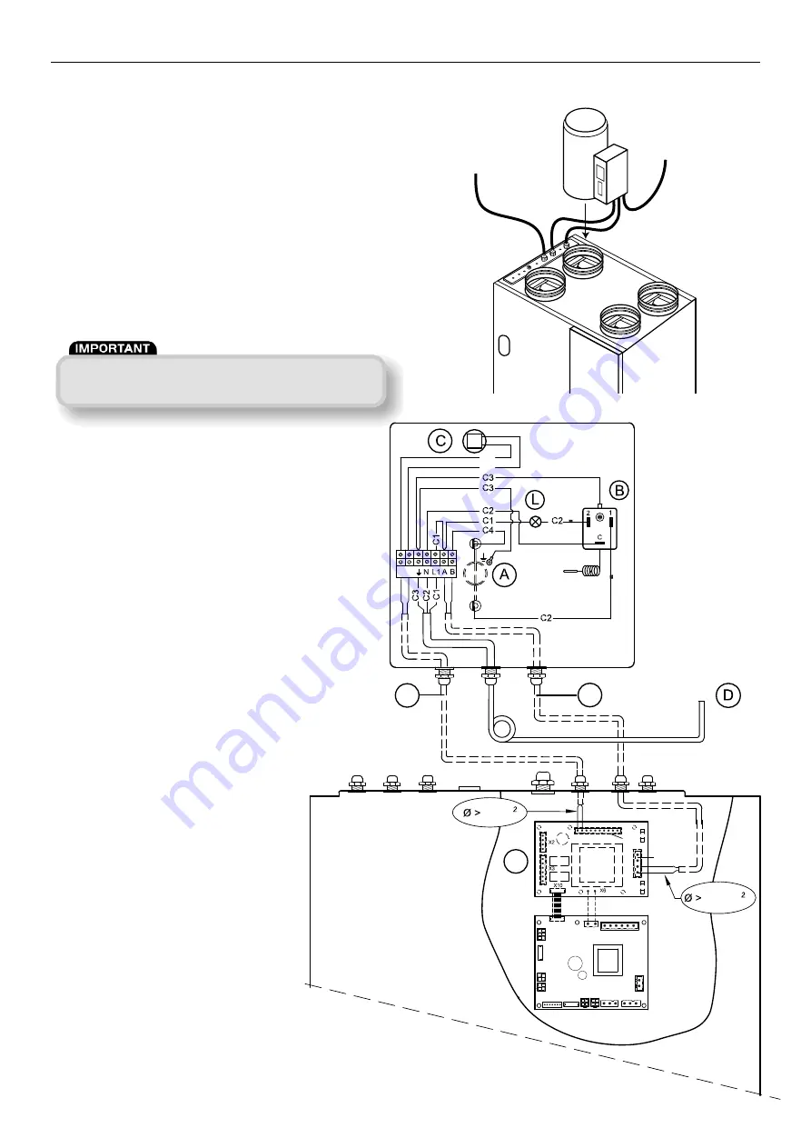
• Connect the wires of the post-heater unit according the
wiring diagram (below) to the required option print.
• Switch on the power supply from the MRXBOX90L unit
as well as the post-heater unit.
I = To
dwelling
2 = To
outside
3 = From
dwelling
4 = From
outside
6.8 Wiring diagram for
post-heater unit
E
X1
E
F
0.4mm
0.75mm
1 2
C5
C5
X4
1
2
4
3
Mains in
Mains in
Figure 15. Typical installation for post-heater
Figure 16.
A = Heating element (max. 1000W)
B = Safety switch for maximum temperature with
manual reset
C = Temperature sensor
D = Power connector 230V
E
= Cable, to be installed and connected
F = Option print (required for this option)
L = 230V LED, lights if safety switch (temperature)
is activated
C1 = Brown
C2 = Blue
C3 = Green/yellow
C4 = Black
C5 = Yellow
The temperature sensor has to be connected
to connector X1 of the MRXBOX90L option pcb.
The control signal for the post-heater unit
has to be connected to connector X4 (230V)
of the MRXBOX90L option pcb.
Technical specifications
Power supply:
230V-50 HZ
Weight:
2.5kg
Duct diameter:
160mm
Protection class:
IP 20
Max. rated power:
1000W
Max. rated current:
4.5A
Settings for post-heater unit
The MRXBOX90L unit needs to be programmed to set the
pre-heater pre-set temperature. This can be done via the
display. (parameter U6, post-heater pre-set temperature).
To change this parameter, please check the installation
guide Large with option print.


