background image

14

Leaflet Number 611272 January 2012

Installation and Maintenance

MRXBOX90L Mechanical Ventilation with Heat Recovery

Step number

Readout (example) 

Description 

Remark

No. 1 

2.200 

Current position/outlet volume m

3

/h

No. 2

CO

Message code operating condition

CO = No message

C3 = The inlet fan runs in constant pressure mode

C6 = The outlet fan runs in constant pressure mode

C7 = Correction maximum air flow

No. 3

bP.1 

Bypass status (only if mounted)

0 = bypass valve shut

1 = bypass valve automatic

2 = Input at minimum

No. 4

tP.9 

Temperature from atmosphere (°C)

At negative temperature (below 0°c) than readout tP.9.

No. 5

tS.21 

Indoor temperature (°C)

No. 6

In.0

n.a.

No. 7

u.156

Current input volume m

3

/h 

No. 8

u.156

Current output volume m

3

/h

No. 9

t.180

Current pressure inlet duct (Pa)

No. 10

A.180

Current pressure outlet duct (Pa)

No. 11

u0.0

Status frost protection

0 = none, 1 - 4 = imbalance, 5 = inlet fan off

No. 12

St.9

Temperature to atmosphere (°C)

If not connected St.75 

(Sensor not connected as standard)

No. 13

Pt.18

Temperature to indoors (°C)

If not connected Pt.75

(Sensor not connected as standard)

Installer

User

7.1 Readouts settings

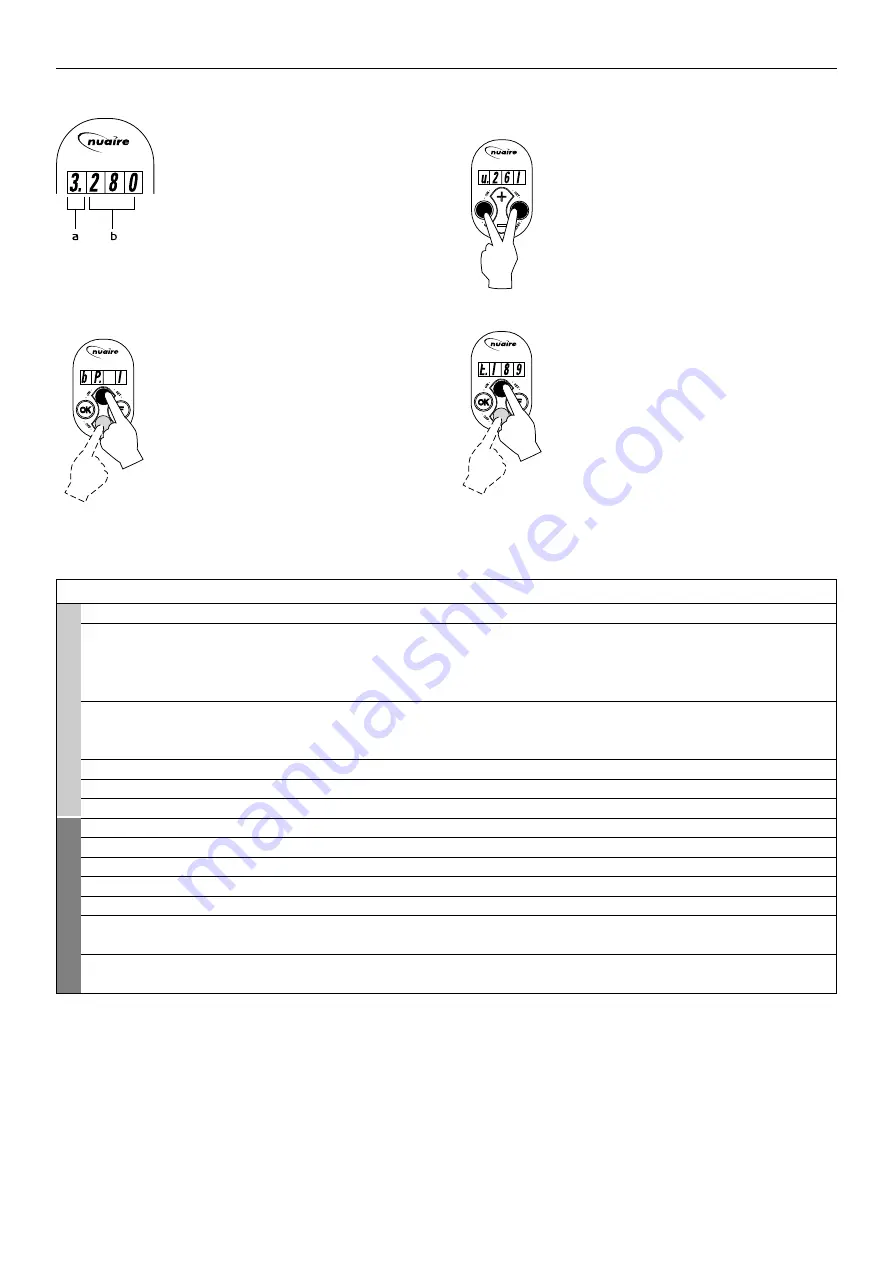
The standard current position of the multiple 

switch and the connected outlet volume are 

shown (operational mode). on the left of the 

multiple switch to the left of the dot. The three 

remaining positions shown to the right of the 

dot represent the volume of the outlet air.

a = position multiple switch is set at

b = volume of outlet air (m

3

/hr)

7.2 Reading out settings 
by the user

The user can read out other relevant data using 

keys 

"+"

and 

"-"

(step 1 - step 6). Step numbers 

are not shown on the display.

See the table below for user readout; if a key is 

not operated during 5 minutes, the display 

automatically returns to operational mode. 

Use key "+" to “scroll” through the menu; press 

key 

"-"

to return to step 1. in this situation no 

settings can be modified.

7.3 Reading out settings by 
the installer

A more comprehensive readout programme is 

available for the installer. All installer data can 

be viewed after pressing keys 

"F"

and 

"OK" 

within 3 seconds. in this menu the values 

cannot be modified.

Activating this menu always calls up step no. 7. 

See the table below for user readout.   

Pressing key 

"+"

calls up the installer and user 

data and pressing key 

"-"

takes you back to 

step no. 1.

After 5 minutes this menu automatically 

disappears and the display will show the 

operational situation again.

In the event of an error, the error code appears 

on the display. Refer to page 18 for further 

information.

Summary of Contents for MRXBOX90L

Page 1: ...es heat transfer between inlet and outlet air 3 Filters filter both air flows 4 Atmospheric temperature sensor measures outside air temperature 5 Communication connection port for cable to multiple sw...

Page 2: ...ol fresh air A Electric connections B Detail wall mounting make sure to correctly place the rubber strip washers and caps C Connection condensate discharge B Detail of wall mounting Air Performance of...

Page 3: ...ctions F Function key switching on and off parameter menu next parameter increase value previous parameter decrease value OK Switching on and off settings menu manual fault reset Other commands can be...

Page 4: ...to emergency mode As standard that is set to switch off the fans 5 0 Installation Installation must be carried out by competent personnel in accordance with the appropriate authority and conforming t...

Page 5: ...if the resistance of the duct system is higher the maximum ventilation capacity will be lower the location of the mechanical ventilation outlet and the sewer stack vent relative to the inlet must be...

Page 6: ...reless Controller optional 1 General If required this optional control see fig 10 can be purchased direct fom Nuaire Part number MRXBOX90 BS Wireless remote control exists from a receiver and a sender...

Page 7: ...n the top and bottom Transmission Range The following figures for expected transmission range may be used as a rough guide only Line of sight connections 30m range in corridors up to 100m in halls Pla...

Page 8: ...sing keys or 5 The modified setting can now A Be saved and stored B Be removed C Be restored to factory setting A Simultaneously press keys F and first press F and then to save the modified setting th...

Page 9: ...ween 3 situations Mode 0 The bypass valve is not operated Mode 1 The bypass valve if installed is opened when standard The temperature conditions are complied with setting Mode 2 The inlet fan starts...

Page 10: ...for pre heater unit E X4 1 2 4 3 Mains in Mains in Figure 12 Typical installation for pre heater Figure 13 A Heating element max 1000W B Safety switch for maximum temperature with manual reset C Powe...

Page 11: ...ce MRXBOX90L Mechanical Ventilation with Heat Recovery Figure 14 6 6 Wiring diagram connection pre heater to MRXBOX90L without option pcb A Heating coil B Maximum safety with manual reset C Connecting...

Page 12: ...igure 15 Typical installation for post heater Figure 16 A Heating element max 1000W B Safety switch for maximum temperature with manual reset C Temperature sensor D Power connector 230V E Cable to be...

Page 13: ...5 minutes Press key OK 1 second If no key is operated during 1 minute Press keys F and OK 3 seconds Press key or Press F or key 1 second Press F or key 1 second Press OK key 1 second If no key is oper...

Page 14: ...of the multiple switch and the connected outlet volume are shown operational mode on the left of the multiple switch to the left of the dot The three remaining positions shown to the right of the dot...

Page 15: ...to activate the settings menu 2 Press keys F and OK for 3 seconds to activate the comprehensive parameters section for the installer 3 The desired parameter can be found with the aid of keys and 4 The...

Page 16: ...ond to reset the filter indication The text FIL will blink for a moment and then the display will return to operational mode 16 Leaflet Number 611272 January 2012 Installation and Maintenance MRXBOX90...

Page 17: ...acing the filters The filter only has to be cleaned when that is indicated on the display it shows the text FIL or if a multiple switch with filter indication is mounted when the red LED at the switch...

Page 18: ...t and the ARC number of the purchase if possible This information will be available on the fan label 11 0 Warranty The 5 year warranty starts from the day of delivery and includes 1 year parts and lab...

Page 19: ...Where access to any part of equipment which moves or can become electrically live are not prevented by the equipment panels or by fixed installation detail eg ducting then guarding to the appropriate...

Page 20: ...20 Leaflet Number 611272 January 2012 Western Industrial Estate Caerphilly United Kingdom CF83 1NA T 029 2088 5911 F 029 2088 7033 E info nuaire co uk W www nuaire co uk...

Reviews: