5.2 Connecting ducts
The air outlet duct does not have to be fitted with a control valve; the
unit itself controls the air quantities.
To prevent condensation on the outside of the outside air inlet duct
and the air outlet duct from the MRXBOX90L unit, these ducts must
be insulated externally vapour-proof as far as the unit.
Pay attention to crosstalk and installation noise, also for incorporated
ducts. Design the duct with separate branches to the valve to prevent
crosstalk. if necessary, the input ducts must be insulated, for instance
when they are installed outside the insulated shell.
A duct diameter, of 180mm is recommended for MRXXBOX90L.
The duct must always have an adequate diameter of 150mm for air
quantities up to 250 m
3
/h, a diameter of 160mm for air quantities up
to 325 m
3
/h and a diameter of 180mm for air quantities up to 400
m
3
/h.
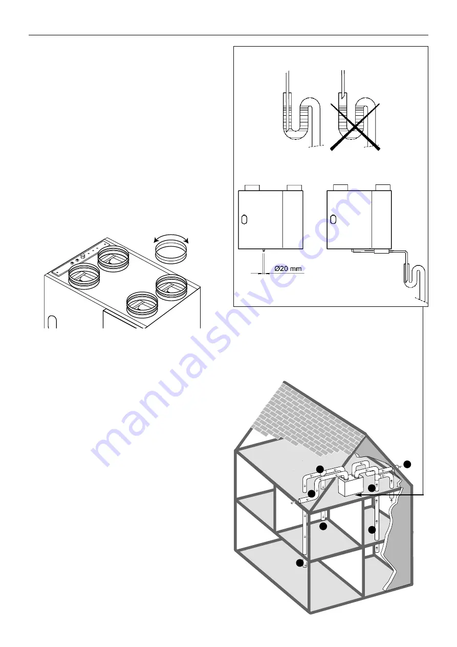
The duct spigots of MRXBOX90L are fitted with eccentric adapters of
180mm diameter. The centre of the connecting duct can be shifted by
rotating these eccentric adapters.
Arrange the exterior air supply from the shadowed (North) side of the
dwelling, for instance from the wall or overhang.
• install the discharge duct between the MRXBOX90L unit and
the roof sleeve in such a manner that surface condensation is
prevented
• always use an insulated ventilation roof sleeve
• the maximum permissible resistance in the duct system is
150 pa at the maximum ventilation capacity. if the resistance of
the duct system is higher, the maximum ventilation capacity will
be lower
• the location of the mechanical ventilation outlet and the sewer
stack vent relative to the inlet must be chosen to prevent
nuisance
• choose the location of the inlet valves to prevent fouling and
draught
5.3 Connecting the condensate discharge
The condensate discharge line for the MRXBOX90L unit is fed
through the lower panel. The condensate must be discharged through
a drainpipe. (see fig. 7a). The drain must discharge under the water
level in the U-trap. The condensate discharge comes separately with
the unit and the installer must screw it into the underside of the unit.
This condensate discharge connection has an external connecting
diameter of 20mm. The condensate discharge line can be glued to it, if
necessary using a square bend. The installer can glue the condensate
discharge in the desired position in the lower part of the unit.
See Figure 7b for an example of a connection to a drainpipe.
Pour water into the drip tray to create an air trap.
5
Leaflet Number 611272 January 2012
Installation and Maintenance
MRXBOX90L Mechanical Ventilation with Heat Recovery
4
2
1
1
3
3
1
Figure 8. Typical installation with unit mounted on wall
Figure 7a. The condensate must be discharged through
a drainpipe.
Figure 6. Eccentric adapters
Ducting references:
1
= to dwelling. Supply (warmed fresh air)
2 = to outside. Exhaust (cool stale air)
3 = from dwelling. Extract (warm stale air)
4 = from outside. Intake (cool fresh air)
Figure 7b. The installer can glue the condensate discharge in
the desired position in the lower part of the unit.


