MRXBOX95-WALL
Mechanical Ventilation Unit with
Heat Recovery for Wall Mounting
Installation and Maintenance
Unit must not be switched off during normal operation, the
product is designed to run continuously.
1.0 Introduction
MRXBOX95-WALL is designed to provide mechanical supply
and extract ventilation with heat recovery.
The unit is fitted with two independent fans. Each fan has full
speed control for background and boost ventilation rates as
well as a run-on timer facility. To recover heat from the extract
air the heat exchanger block is utilised. This heat exchanger
can recover up to 95% of the normally wasted heat.
2.0 Installation
Installation must be carried out by competent personnel in
accordance with the appropriate authority and conforming
to all statutory governing regulations.
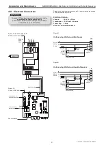
All mains wiring must be in accordance with the current I.E.E.
Regulations, or the appropriate standards. Ensure that the
mains supply (Voltage, Frequency and Phase) complies with
the rating label.
Please note a clear working space is required around the
installed unit to allow the cover to be removed and provide
sufficient access for maintenance such as filter change.
The fan must be installed indoors, on a wall away from direct
sources of frost, heat, water spray or moisture generation. For
a vibration-free result the unit must be mounted to a solid wall.
The unit is designed for wall mounting only.
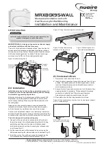
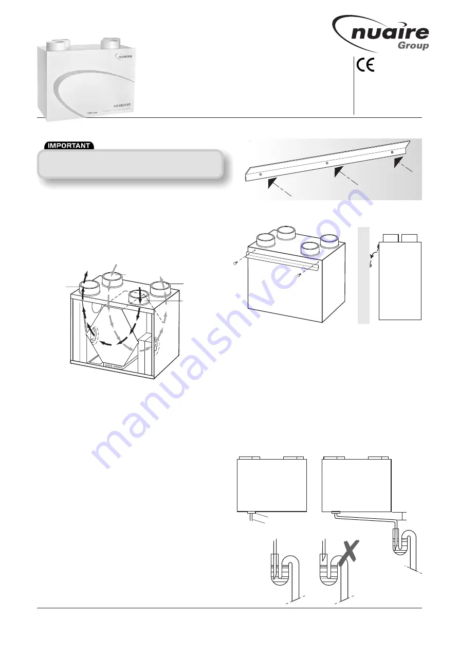
1. One part of the mounting bracket should be offered up to
the wall, ensuring it’s located horizontally. Mark the fixing
points through the pre drilled holes in the bracket and
install with screws (by others), ensuring the interlock side
is at the top (fig. 2).
2. Fix the remaining part of the bracket to the unit using the
M6 screws ensuring the interlock side is at the bottom (fig. 3).
3. Install the unit on the wall by ensuring the bracket on the
unit interlocks over the wall mounted bracket (fig. 4).
2.1 Condensate Drain
1.
Remove the front cover from the unit.
2. Insert the drain connector through the base of the unit from
outside. The condensate must be discharged under a water
level in a U-trap drainpipe or an alternative drain method
which acts as an airlock.
3. Ensure the drain connector forms a seal with the drain tray
applying sealant if necessary. This condensate discharge
connection is suitable for 21.5mm dia. overflow pipe.
Solvent cement should be used to make the joint.
4. Pour water into the drip tray to create an air trap.
Nuaire Limited
Western Industrial Estate Caerphilly United Kingdom CF83 1NA
T: 029 2085 8400 F: 029 2085 8444 E: info@nuaire.co.uk W: www.nuaire.co.uk
1
02. 07. 15. Leaflet Number 671437
Extract air
from house
Intake air
from outside
Exhaust air
from house
to outside
Supply air
to house
Figure 1. Airflow through unit.
The EMC Directive
2004/108/EC
The Low Voltage
Directive
2006/95/EC
Figure 3. Fixing the mounting
bracket to the rear of unit.
Figure 4. Mounting the unit
on the wall mounted bracket.
Figure 5. Condensate pipe connection to unit and a typical example
of a “U” trap drainpipe.
Figure 2. Fixing the mounting bracket to the wall.
21.5mm dia. condensate pipe.
See point 3 above for sealing.
5
o
Drop
Collar

