4
02. 07. 15. Leaflet Number 671437
Installation and Maintenance
MRXBOX95-WALL Mechanical Ventilation with Heat Recovery
Electrical connection cont.
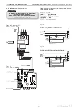
Figure 10. Detail of unit control on front panel.
Optional Connections
Ecosmart control
(see figure 7b)
(a) J11/12/13
The IDC plug-in connectors are provided for the connection of
compatible sensors.
NOTE: Do not run the data cable in the same conduit as the
mains cable and leave a 50mm separation with any power
cables.
(b) Volt Free Relay Contacts
Note that the volt free contacts are not fused. If these are used
to power any external equipment, the installer must provide
adequate fusing or other protections. These contacts are rated
at 5A resistive, 0.5A inductive.
Run connections (J5)
- These contacts are closed when the
fan is running.
Fault connections (J7)
- No fault = the contacts are closed.
Fault
= the contacts are opened (this includes no power supply
at the unit).
(c) Data Cable installation
A 4-core data cable is used to connect devices such as sensors
to the fan and for interconnecting multiple fan units.
Do not run data cable in the same conduit as the mains cables
and ensure there is a 50mm separation between the data cable
and other cables. The maximum cable run between any two
devices is 300m when it is installed in accordance with the
instructions.
Please note that the total data cable length used in any system
must be less than 1000m. Keep the number of cable joints to a
minimum to ensure the best data transmission efficiency
between devices.
LED Indication
PWR GREEN:
Power on and OK,
RED:
Standby LED on when fan is not running.
As the unit runs continuously this LED should
be off. If it is illuminated locate the trickle
switch and change its position.
Fan 1 GREEN:
Fan 1 is running,
RED:
Fan 1 faulty.
Fan 2 GREEN:
Fan 2 is running,
RED:
Fan 2 faulty.
5.0 Ancillaries
Passive Infra red detector
MRXBOX95-PIR
External Humidity sensor
MRXBOX95-HUM
Remote Fail Indicator
MRXBOX95-RFI
6.0 Commissioning
1.
For the required airflow rates refer to the design
specification for the property or refer to Building
Regulations Part F.
2.
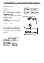
The unit is supplied with control of both the normal
airflow and boost airflow. (see figure below).
3.
Commissioning should be carried out using a moving
vane anemometer in conjunction with a hood.
4.
Once commissioned the house owner / tenant should
be informed that the unit should not be adjusted as it
will have a detrimental effect on the indoor air quality
and could result in condensation and mould growth.


