background image

3

08. 05. 14. Leaflet Number 671588

Installation and Maintenance

MRXBOX95-WM2 Mechanical Ventilation with Heat Recovery

603

503

Mounting 

bracket

353

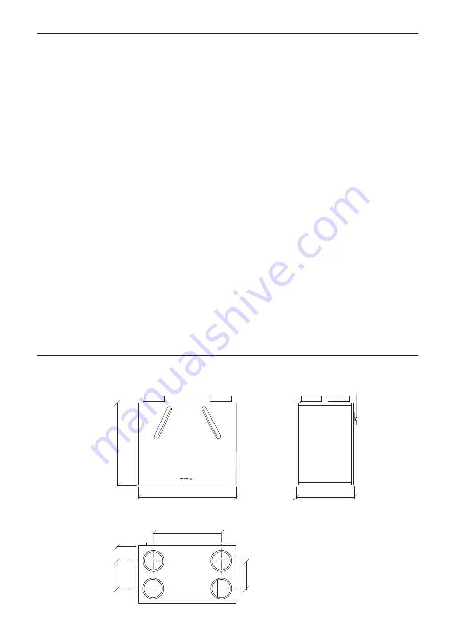
Side view

Front view

View from top

Spigots 

4 x 125mm dia.

419

90

172

172

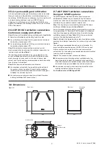
3.0 Dimensions 

Figure 6. 

2.5 Air permeability and infiltration

Is the uncontrolled exchange of air between inside and outside

through cracks, porosity and other unintentional openings in

the building. ADF2006 gives an allowance for this in both multi

and single storey buildings, however ADF2010 has an

allowance for multi storey only. Additionally ADF2010  only

applies this allowance for dwellings leaker than 5 m

3

/(h.m

2

) at

50Pa. (See below).

2.6 ADF 2006 Ventilation calculations

Continuous supply and extract

Step 1: 

Determine the whole building ventilation rate 

from Table

2.

Allow for infiltration by subtracting from this value:

n

for multi-storey dwellings: 0.04 x gross internal volume of 

the dwelling heated space (m

3

);

n

for single-storey dwellings: 0.06 x gross internal volume of 

the dwelling heated space (m

3

).

Step 2: 

Calculate the whole dwelling air extract rate at 

maximum operation by summing the individual room rates for

‘minimum high rate’ 

from Table 1.

(For sanitary accommmodation only, as an alternative, the

purge ventilation provisions given in ADF 2006 can be used

where security is not an issue. In this case ‘minimum high

extract rate’ for the sanitary accommodation should be omitted

from the step 2 calculation).

Step 3: 

The required airflow rates are as follows:

n

the maximum extract rate (e.g. boost) should be at least 

the greater of step 1 and step 2. Note that the maximum 

individual room extract rate should be at least those given 

in table 1

. for minimum high rate.

n

the minimum air supply rate should be at least the whole 

building ventilation rate found in step 1.

2.7 ADF 2010 Ventilation calculations

Design of MVHR systems

The MVHR system has been sized for the winter period.

Additional ventilation may be required during the warmer

months and it has been assumed that the provisions for purge

ventilation (e.g. openable windows) could be used.

Step 1:

For any design air permeability, determine the whole

dwelling ventilation supply rate 

from Table 2.

As an alternative where the design air permeability is intended

to be leakier than (>) 5m

3

/(h.m

2

) 50 Pa, allow for infiltration

for all dwelling types by subtracting from the whole dwelling

ventilation supply rate 

from Table 2

; 0.04 x gross internal 

volume of the dwelling heated space (m

3

).

Step 2:

Calculate the whole dwelling extract ventilation rate by

summing the individual room rates for ‘minimum high rate’ 

from

Table 1.

(For sanitary accommmodation only, as an alternative, the

purge ventilation provisions given in ADF 2010 can be used

where security is not an issue. In this case ‘minimum high

extract rate’ for the sanitary accommodation should be omitted

from the step 2 calculation).

Step 3: 

The required airflow rates are as follows:

n

the maximum whole dwelling extract ventilation rate (e.g. 

boost) should be at least the greater of step 1 and step 2. 

Note that the maximum individual room extract rate should 

be at least those given

in table 1.

for minimum high rate.

n

the minimum air supply rate should be at least the whole 

building ventilation rate found in step 1.

For Scotland refer to BRE Digest 398.

Summary of Contents for MRXBOX95-WM2

Page 1: ...le wall away from direct sources of frost heat water spray or moisture generation For a vibration free result the unit must be mounted to a solid wall The unit is designed for wall mounting only via a patress 1 One part of the mounting bracket should be offered up to the wall ensuring it s located horizontally Mark the fixing points through the pre drilled holes in the bracket and install with scr...

Page 2: ... minimum A minimum distance of 200mm between the appliance and any bends in ductwork is recommended Ideally 150mm diameter or 204 x 60mm rectangular ducting should be used Refer to dwelling design drawing figure 7a and 7b on page 4 for further information Ducting joints must be sealed with silicone type sealant and shall be adequately and reliably fixed to the appliance 2 4 Ventilation flow rates ...

Page 3: ...east the greater of step 1 and step 2 Note that the maximum individual room extract rate should be at least those given in table 1 for minimum high rate n the minimum air supply rate should be at least the whole building ventilation rate found in step 1 2 7 ADF 2010 Ventilation calculations Design of MVHR systems The MVHR system has been sized for the winter period Additional ventilation may be re...

Page 4: ...um 300mm Air supply to lounge via Air Valve Part no VS125 in ceilings Extract air from kitchen bathroom via Air Valve Part no VS125 in ceilings Air supply to bedrooms via Air Valve Part no VS125 in ceilings Top of ceiling void Top of ceiling void Nuaire MRXBOX95 WM2 wall mounted unit on a patress Air supply to bedrooms via Air Valve Part no VS125 in ceilings Nuaire MRXBOX95 WM2 wall mounted unit o...

Page 5: ...olator 3 Pole isolator Kitchen switch Kitchen switch Blue Brown Black Optional summer boost switch Supply cord from unit Green yellow Blue Brown Black Supply cord from unit Optional summer boost switch Grey Grey Green yellow Unit serving kitchen and bathroom Unit serving kitchen and two bathrooms Figure 9 Figure 10 SWL2 L SWL1 L N CN7 EXTRACT CN6 SUPPLY BLU WHI YEL RED SUPPLY BYPASS SUPPLY FAN EXT...

Page 6: ...e removed post commissioning to prevent tampering 6 1 Summertime boost facility The unit has to ability to override both the trickle and boost speeds to operate the fan to maximum airflow See wiring diagram for details of operating this facility 7 0 Status Indication The status of the unit is indicated by a series of LED s on the front cover The varients are listed below 8 0 Maintenance Cleaning W...

Page 7: ...ange speed This is normal and will have no adverse effect on the fan The speed will return to normal once the interference has subsided 5 0 INSTALLATION REQUIREMENTS In addition to the particular requirements given for the individual product the following general requirements should be noted 5 1 Where access to any part of equipment which moves or can become electrically live are not prevented by ...

Page 8: ...CF83 1NA T 029 2085 8400 F 029 2085 8444 E info nuaire co uk W www nuaire co uk Technical or commercial considerations may from time to time make it necessary to alter the design performance and dimensions of equipment and the right is reserved to make such changes without prior notice ...

Page 9: ...lings assessed under The Building Regulations 2010 specifically SAP 2009 and Approved Documents L and F Completion of this document is therefore only required for dwellings assessed by SAP 2005 Customer Details Customer Name Address Telephone Number Date of Installation Name of Lead Contractor Design Project Number It should be noted that this guidance is not intended to replace product manufactur...

Page 10: ...or to overcome particular obstructions If flexible ducting has been used has it been pulled taut to minimise system resistance Has the number of duct bends been minimised to ensure adequate air flow and least resistance Bends should have a minimum radius at least the same as the diameter of the ducting used Refer to Figure 1 if using flexible ducting Have the fans and ducting placed in unheated vo...

Page 11: ...ry unit been fixed to a stable element of the building fabric e g wall or floor using manufacturer recommended supplied fixing brackets Has the condensation drain been fitted and the pipe insulated Have approved acoustic anti vibration mountings been used Note Special attention is needed to avoid transmission and stress to duct joints Has the unit been installed in a position that will permit acce...

Page 12: ... or N A Has the rating label been verified to establish suitability for the installation strategy and whether an earth is required e g voltage class I or II product status Has a local isolator been provided to enable the unit to be isolated for maintenance purposes Has the unit been fused in accordance with its power rating SECTION 2 COMMISSIONING GUIDANCE ...

Page 13: ...ution grilles been locked where possible to minimise unapproved occupant adjustment Figure 3 Ensure all external and internal windows and doors are closed Set fan speed using manufacturer data table Set normal daytime air flow on extract points starting at location furthest from unit Set normal daytime air flow on input points starting at location furthest from unit Step 1 Step 2 Step 3 Step 4 Ste...

Page 14: ...he customer been advised that opening windows is not recommended during normal use in order to ensure the energy efficient operation and performance of the balanced system Has the customer been advised not to seal natural air flows from room to room e g avoid door seals and thick pile carpets Has the customer been advised not to alter settings post commissioning Has the customer been advised to cl...

Reviews: