2.1 Condensate Drain installation
1.
Unit comes complete with external drain pipe (21.5mm waste
pipe). Use conventional plumbing connections to link up with
U-trap or alternative drain method (Solvent cement
connections or compression fit connections are
recommended). The condensate must be discharged under a
water level in a U-trap drainpipe or an alternative drain
method which acts as an airlock.
2. This condensate discharge connection is suitable for 21.5mm
dia. overflow pipe. Solvent cement should be used to make
the joint.
3. If using a U-trap please ensure the U-trap has been filled to
a suitable level of water to avoid any air locks.
4. If the condensation pipe is fitted in an unheated space the
pipe should be in insulated to prevent freezing.
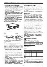
Nuaire recommend MVHR-DRAIN be used as the primary
condensate take-off. (see figures 4a and 4b).
Fixing
Offer up the MVHR-DRAIN inlet to the threaded tail of the
appliance waste outlet or MVHR-DRAIN knuckle or running
adaptor, and tighten the threaded cap sufficiently hand-tight to
provide a water-tight seal (check that the cap screws on square
and does not ‘cross-thread’). When the screwed cap is tight, the
MVHR-DRAIN
body is secure.
1. Cut the pipe to length, allowing for the full compression
socket depth (using an appropriate pipe cutter, such as a
Hepworth rachet pipe cutter).
2. Remove any ‘swarf’ from the end of the plastic pipe.
Ream the copper pipe end to remove any ‘burr’, and file if
necessary to remove any external sharp edges. Mark the
socket depth on the pipe, and check that the pipe section to
be jointed is free of any surface damage which may affect
the joint seal.
3. Unscrew the cap from the MVHR-DRAIN outlet, and slide the
cap and rubber seal onto the pipe.
4. Insert the pipe end fully into the socket.
5. Slide the rubber seal and screwed cap up against the face of
the socket, and tighten the cap sufficiently hand-tight (check
that the cap is square to the body and does not ‘cross-
thread’). Hand tight should be adequate to form a proper seal.
2.2 Extract/input areas
The unit is designed to extract air from all wet rooms
e.g. bathroom, kitchen, en-suite, utility room (with sink).
WC’s do not need to be ventilated if openable windows are fitted.
Supply air should be to all habitable rooms e.g. bedrooms and
lounge. Extract / input grilles should be adjustable valve types
(not supplied).
External grilles to have a minimum free area of 12,250 sq mm.
2.3 Ducting
Before commencing ducting installation reference should be
made to building regulations document “Domestic ventilation
compliance guide”. This document supports ADF2010 and
details installation, testing and commissioning of all ventilation
systems.
It is recommended that rigid ducting must be used it all times.
Flexible ducting has a very high resistance and it is impossible
to calculate how much resistance will be on a system if used.
If used the flexible ducting must be kept to a minimum and
should always be pulled taut. A maximum of 300mm should
be used on each leg.
To prevent condensation on the outside of the outside air inlet
duct and the air outlet duct from the MRXBOX95B-LP1EH,
these ducts should be insulated.
Ducting must be installed in such a way that resistance to
airflow is minimised. Bends should be kept to a minimum.
A minimum distance of 200mm between the appliance and
any bends in ductwork is recommended.
204 x 60mm rectangular ducting should be used. (Refer to
dwelling ducting design drawing, figure 6 on page 4 for further
information).
Ducting joints must be sealed with silicone type sealant and
needs to be taped. Ducting shall be adequately and reliably
fixed to the appliance.
2.4 Ventilation flow rates
Table 1.
ADF2006 / 2010 – Extract ventilation rates
Room
Min high rate
Min low rate
Kitchen
13 l/s
Utility room
8 l/s
Bathroom
8 l/s
Sanitary
accommodation
6 l/s
Table 2.
Whole dwelling ventilation rates
Number of bedrooms in dwelling
1
2
3
4
5
Whole
13
17
21
25
29
dwelling
ventilation
rate l/s
1, 2
Notes:
1, In addition, the minimum ventilation rate should be not less than 0.3 l/s
per m2 of internal floor area.
(This includes all floors, e.g. for a two-story building add the ground and
first floor areas).
2, This is based on two occupants in the main bedroom and a single occu-
pant in all other bedrooms. This should be used as the default value. If a
greater level of occupancy is expected add 4 l/s per occupant.
2
05. 09. 13. Leaflet Number 671632
Installation and Maintenance
MRXBOX95B-LP1EH Mechanical Ventilation with Heat Recovery & Summer Bypass
Figure 4a. MVHR-DRAIN condensate drain, running to SVP.
Total extract rate should
be at least the whole
dwelling ventilation rate
given in table 2.
Figure 4b. MVHR-DRAIN correct installation.
RIGHT
WRONG
Flow
Side elevation
When installed horizontally the ribs must be at the bottom to
ensure correct operation.


