2
15. 03. 21. Document Number 671857
Nuaire |
Western Industrial Estate
|
Caerphilly
|
CF83 1NA
|
nuaire.co.uk
MRXBOXAB-ECO4-(SC/SW)
Installation Manual
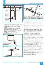
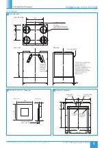
Care must be taken to ensure the unit is installed true in all 3
dimensions. Failure to do so may result in overflow from the
internal condensation drip tray.
If fitting the MVHR in conjuntion with a MRXBOX-SIL4 the unit
should be mounted using alternative brackets supplied under part
code MRXBOX-AV4, the standard wall brackets supplied with the
MVHR are not rated for the additional load.
•
One part of the mounting bracket (supplied) should be offered
up to the wall, ensuring it’s located horizontally. Mark the fixing
points through the pre drilled holes in the bracket and install with
screws (by others), whilst ensuring the interlock side is at the top
(Figure 3).
•
Install the unit on the wall by ensuring the bracket on the unit
interlocks over the wall mounted bracket (Figure 4). Ensure the
mains power cable does not become trapped between the brackets
during this process as this will prevent engagement and potentially
damage the electrical insulation. The cable gland can be rotated
through 90° to assist this operation and subsequent cable routing.
3
Wall Mounting Bracket
3.1 Solid Wall Mounting
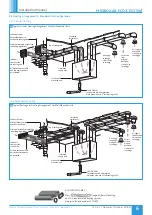
The MVHR unit fixed to a solid wall construction using a suitable
mounting structure (supplied by others).
Ducting in the
ceiling void.
Side view of unit
mounted on the
block wall in a
cupboard.
MVHR-DRAIN
Condensate drain,
uninsulated drain
pipe with min 5
o
fall running to SVP.
Valve in ceiling.
4
Solid Wall Mounted Unit Installation
3.2 Non-Solid Wall Mounting
The unit is designed for wall mounting, only on a solid wall. A
gypsum block or stud/plasterboard wall will not suffice.
If it is not practical to use a solid wall, the MVHR unit should be
fixed to a stud partition with a 25mm minimum thickness MDF
panel solidly fixed behind the plasterboard.
If fixing to a stud wall the MDF panel should extend, width wise, over a
minimum of 3 vertical studs with centres of no more than 400mm. Add
additional vertical supports if necessary. Height wise, ideally, the MDF
panel should extend from floor to ceiling but as a minimum should be a
least 2m high.
Fix the mounting bracket to the wall (Figure 3) and use the wall
mounted bracket to mount the unit on (Figure 5).
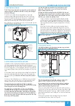
2.0 INTRODUCTION
The ECO4 wall mounted units are designed to provide mechanical
supply and extract ventilation with heat recovery and an integral
automatic HX bypass.
The MVHR unit is fitted with two independent fans to provide
mechanical supply and extract ventilation, each fan has full speed
control for background and boost ventilation rates. To recover heat
from the extract air, the heat exchanger block is utilised. The heat
exchanger can recover up to 95% of the normally wasted heat.
Bypass operation can be disabled via a manual switch in colder months
so the unit recovers heat continually.
Extract air
from house
Intake air
Exhaust air
from outside
to outside
from house
to house
Supply air
Intake air
from outside
Extract air
from house
Supply air
to house
Exhaust air
from house
to outside
1
Airflow Through unit (Standard Hand Unit)
Extract air
from house
Intake air
Exhaust air
from outside
to outside
from house
to house
Supply air
Intake air
from outside
Extract air
from house
Supply air
to house
Exhaust air
from house
to outside
2
Airflow Through OH unit (Opposite Hand Unit)
3.0 MECHANICAL INSTALLATION
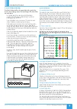
Installation must be carried out by competent personnel in accordance
with the appropriate authority and conforming to all statutory
governing regulations. All mains wiring must be in accordance with the
current I.E.E. Regulations, or the appropriate standards. Ensure that the
mains supply (Voltage, Frequency and Phase) complies with the rating
label.
A clear working space is required around the installed unit to allow the
cover to be removed and provide sufficient access for maintenance
such as filter change.
A minimum of 480mm is required in front of
the unit.
The fan must be installed indoors, on a suitable wall away from direct
sources of frost, heat and water spray or moisture generation. For a
vibration-free result the unit must be mounted to a solid wall.
The unit must remain switched on at all times to maintain
ventilation within the dwelling. Turning the unit off will cause long
term damage to the unit and building fabric.
This appliance is not intended for use by persons (including
children) with reduced physical, sensory or mental capabilities,
or lack of experience and knowledge, unless they have been given
supervision or instruction concerning the use of the appliance by a
person for their safety. Children should be supervised so that they
do not play with the appliance.

