3
15. 03. 21. Document Number 671857
Nuaire |
Western Industrial Estate
|
Caerphilly
|
CF83 1NA
|
nuaire.co.uk
MRXBOXAB-ECO4-(SC/SW)
Installation Manual
5
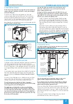
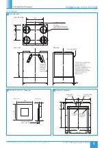
Non-Solid Wall Mounted Unit Installation
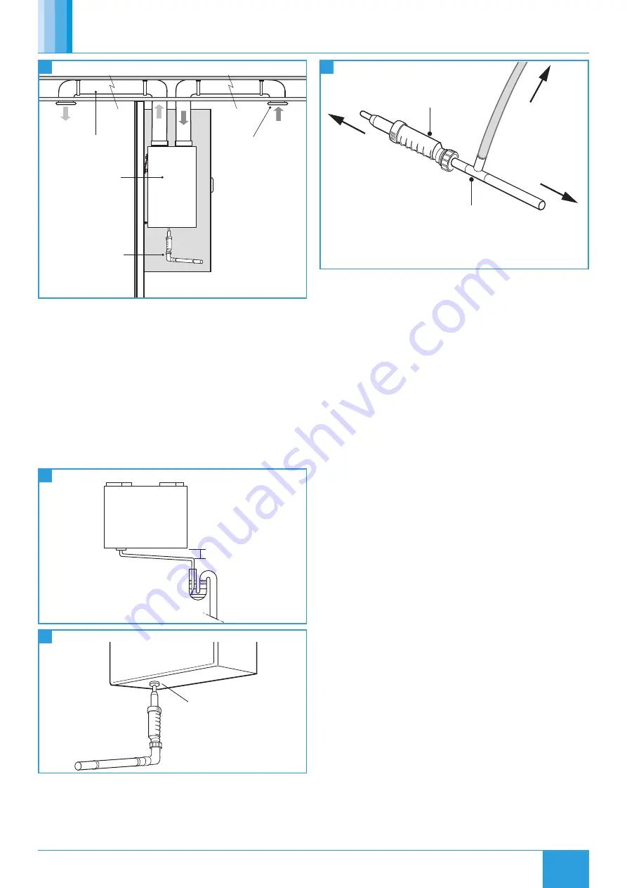
Ducting in the
ceiling void.
mounted in a
Side view of unit
a stud partition
cupboard fixed to
with the 25mm
MDF fixed behind
MVHR-DRAIN
the plasterboard.
Condensate drain,
uninsulated drain
pipe with min 5
o
fall running to SVP.
Valve in ceiling.
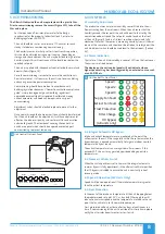
3.3 Condensate Drain
•
The condensate must be discharged under a water level in a U-trap
drainpipe or an alternative drain method which acts as an airlock.
•
The condensate discharge drain is a 32mm male threaded
connection.
•
If using a U-trap, please ensure the U-trap has been filled to a
suitable level of water to avoid any air locks.
•
If the condensation pipe is fitted in an unheated space the pipe
should be in insulated to prevent freezing.
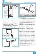
An MVHR-DRAIN is recommended for use as the primary
condensate take-off (Figures 7 and 8).
Min 5
o
Drop
6
Condensate Trap Installation
Condensate pipe connection to
unit and a typical example of a
“U” trap drainpipe
(Standard
configuration only).
Collar
7
MVHR-DRAIN Installation
Condensate drain,
uninsulated drain pipe with
min 5° fall running to SVP.
To SVP
“T” piece
MVHR Drain
To unit
To CONTRAP
8
"T" Piece CONTRAP & MVHR Drain Connection
When using a “T” Piece to connect the CONTRAP drainage and
the MVHR drain pipework the MVHR drain must always be fitted
before the “T” Piece to prevent condensate from feeding back into
the MVHR system.
3.4 Extract / Input Areas
The unit is designed to extract air from all wet rooms e.g. bathroom,
kitchen, en-suite, utility room (with sink). WC’s do not need to be
ventilated if openable windows are fitted.
Supply air should be to all habitable rooms e.g. bedrooms and lounge.
Extract / input grilles should be adjustable valve types (not supplied).
External grilles are to have a minimum free area of 12,250 sq. mm.
3.5 Ducting
Before commencing ducting installation, reference should be made
to building regulations document “Domestic ventilation compliance
guide”. This document supports ADF2010 and details installation,
testing and commissioning of all ventilation systems.
If the enclosure is to be used in conjunction with an ancillary
distribution box (MRXBOX-DB4) refer to additional assembly
instructions supplied with the MRXBOX-DB4 as requirements will
differ.
Otherwise fit 4x 200mm diameter spigots with the M4 screws supplied
to the spigot fixings plates found on the top panel of the enclosure, a
bead of silicone should be applied between the two mating faces to
prevent leakage.
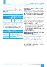
It is recommended that rigid ducting be used at all times. Flexible
ducting has a very high resistance and it is impossible to calculate
how much resistance will be on a system if used. If used the flexible
ducting must be kept to a minimum and should always be pulled taut.
A maximum of 300mm should be used on each leg.
To prevent condensation on the outside of the outside air inlet duct and
the air outlet duct from the unit, these ducts should be insulated.
Ducting must be installed in such a way that resistance to airflow is
minimised. Bends should be kept to a minimum. A minimum distance
of 300mm between the appliance and any bends in ductwork is
recommended.
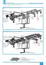
Ideally 150mm diameter or 220 x 90mm rectangular ducting should be
used (refer to dwelling design drawing, Figures 12 & 13).
Ducting joints must be sealed with silicone type sealant and shall be
adequately and reliably fixed to the appliance.

