background image

7

15. 03. 21. Document Number  671857

Nuaire | 

Western Industrial Estate 

Caerphilly 

CF83 1NA 

|


nuaire.co.uk

MRXBOXAB-ECO4-(SC/SW)

Installation Manual

4.0 ELECTRICAL INSTALLATION

For good EMC engineering practice, any sensor cables or switched 
live cables should not be placed within 50mm of other cables or on 
the same metal cable tray as other cables.

The electrical connection of the unit must be carried out by a qualified 

electrician. The unit is supplied with a flexible cord for connection to 

the mains supply.
Wiring is for reference purposes only, connections shown are factory 

fitted. The unit is pre-wired with a 2 metre fly lead.

Disconnection from the supply mains must be incorporated within 

the fixed wiring in accordance with the wiring regulations and shall 

have a minimum contact separation of 3mm.

4.1 Electrical Information

Voltage: 240V  1ph  50Hz 

Consumption: 2.5 Amp 
This unit must be earthed.
The cable from the mains power supply should be connected to a 

fixed wiring installation, via a fused isolator, in accordance with 

current IEE wiring regulations.

4.2 Wiring Diagrams

4.2.1 Unit Only


14 

Wiring Diagram - Unit Only

MAINS
230V
50Hz

N

L

3 Position Switch Ancillary code: 
MRXBOX95-3SWITCH

Blue

Green/yellow

Brown

Black

Supply cord
from unit

Grey

L

1

2

5A Fuse

(BS1362)

2 Pole
Isolator

4.2.2 Unit Serving One Bathroom

15 

Wiring Diagram - Unit Serving One Bathroom

5A Fuse

(BS1362)

MAINS
230V
50Hz

N

L

3 Pole 
Isolator

3 Position Switch Ancillary code: 
MRXBOX95-3SWITCH

Blue

Green/yellow

Brown
Black

Supply cord
from unit

Grey

L

1

2

light

Room 

Light Switch

(Double Pole)

4.2.3 Unit Serving Two Bathrooms

16 

Wiring Diagram - Unit Serving Two Bathrooms

5A Fuse

(BS1362)

Light Switches

(Double Pole)

MAINS
230V
50Hz

N

L

3 Pole 
Isolator

3 Position Switch Ancillary code: 
MRXBOX95-3SWITCH

Blue

Green/yellow

Brown
Black

Supply cord
from unit

Grey

L

1

2

Room 
lights

4.2.4 Summer / Winter Switch

17 

Wiring Diagram - Summer / Winter Switch

Black

2 core cable
from unit

Red

Volt free Summer / Winter Switch (supplied with unit)
Polarity is inconsequential
Warning! - Do not connect to mains! 

LI

AF


Supply    Supply    Extract    Extract

Speed1   Speed2    Speed1    Speed2

21 

PCB Details

Summary of Contents for MRXBOXAB-ECO4-OHSC

Page 1: ...erson responsible for their safety Children shall not play with the appliance Cleaning and user maintenance shall not be carried out by children 1 1 Hazard Symbols REFER TO INSTRUCTION MANUAL Read and...

Page 2: ...nted bracket to mount the unit on Figure 5 2 0 INTRODUCTION The ECO4 wall mounted units are designed to provide mechanical supply and extract ventilation with heat recovery and an integral automatic H...

Page 3: ...o not need to be ventilated if openable windows are fitted Supply air should be to all habitable rooms e g bedrooms and lounge Extract input grilles should be adjustable valve types not supplied Exter...

Page 4: ...where the design air permeability is intended to be more than 5m3 h m2 50 Pa allow for infiltration for all dwelling types by subtracting from the whole dwelling ventilation supply rate from Whole Dwe...

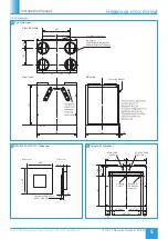
Page 5: ...485 710 710 585 Ecosmart connection 4 x Spigots 180mm Internal Diameter 200mm External Diameter View from top Side view Front view 18 Mounting Bracket AB AB 200 176 534 67 492 CRS 67 40 0 CRS 5 Fixing...

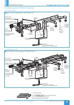
Page 6: ...r Valve mounted unit Nuaire wall MVHR DRAIN Condensate drain uninsulated drain pipe with min 5o fall running to SVP Insulated extract duct 3 9 2 Rectangular Ducting 13 Typical Rectangular Ducting Arra...

Page 7: ...ring installation via a fused isolator in accordance with current IEE wiring regulations 4 2 Wiring Diagrams 4 2 1 Unit Only 14 Wiring Diagram Unit Only MAINS 230V 50Hz N L 3 Position Switch Ancillary...

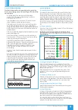
Page 8: ...Humidity Adjustment This product contains an internal humidity sensor fitted into the air flow extracting from the wet rooms When the unit senses that the humidity exceeds the set point the unit will...

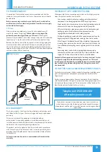
Page 9: ...ate attached to the unit casing Telephone 02920 858 400 aftersales nuaire co uk Technical or commercial considerations may from time to time make it necessary to alter the design performance and dimen...

Page 10: ...10 15 03 21 Document Number 671857 Nuaire Western Industrial Estate Caerphilly CF83 1NA nuaire co uk MRXBOXAB ECO4 SC SW Installation Manual NOTES...

Page 11: ...11 15 03 21 Document Number 671857 Nuaire Western Industrial Estate Caerphilly CF83 1NA nuaire co uk MRXBOXAB ECO4 SC SW Installation Manual NOTES...

Page 12: ...12 15 03 21 Document Number 671857 Nuaire Western Industrial Estate Caerphilly CF83 1NA nuaire co uk MRXBOXAB ECO4 SC SW Installation Manual NOTES...

Reviews: