8
15. 03. 21. Document Number 671857
Nuaire |
Western Industrial Estate
|
Caerphilly
|
CF83 1NA
|
nuaire.co.uk
MRXBOXAB-ECO4-(SC/SW)
Installation Manual
5.0 COMMISSIONING
The filters fitted inside the unit are protected with a plastic film.
Prior to commissioning remove the covers (Figure 201), take off the
film and replace.
•
For the required air flow rates please refer to the design
specification for the property, follow Section 3.7, or refer to
building regulations ADF 2010.
•
The unit should be run for a minimum of 10 minutes to reach
steady state before commencing commissioning.
•
The humidity sensor is initially set to its least sensitive position,
this should be adjusted during commissioning. Depending on
storage and site conditions, the unit may boost due to high relative
humidity levels, this will continue until the level drops below the
specified set point.
•
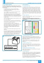
The unit is supplied with independent control for both normal and
boost airflows (Figure 19).
•
Correct commissioning is essential to ensure the ventilation air
flow rates are met. It also ensures the unit is not over ventilating
and causing excessive power consumption.
•
Commissioning should be carried out in accordance with
building regulations document “Domestic ventilation compliance
guide”. www.planningportal.gov.uk/building regulations/
approved documents/partf/associated. A calibrated moving
vane anemometer and hood will be required to carry out
commissioning.
•
Adjustment valves should be locked in place to prevent further
adjustment.
•
Once commissioned the home owner / tenant should be informed
that the unit should not be adjusted as it will have a detrimental
effect on the indoor air quality and could result in condensation
and mould growth. The clear panel covering the control has
an adhesive panel which should be exposed and sealed post
commissioning to prevent tampering.
+
-
Post commissioning remove
adhesive backing and seal
061021
Power Fan
Failure
+
-
Ventilation Controls
- +
+
- +
-
Speed 1
- +
Speed 2
Speed 3
Supply Extract Supply Extract Supply Extract
18
Unit Control On Front Panel
6.0 CONTROLS
6.1 Humidity Adjustment
This product contains an internal humidity sensor fitted into the air-
flow extracting from the wet rooms. When the unit senses that the
humidity exceeds the set point the unit will boost to that set by the
commissioned boost speed. The set point can be found on the front
of the unit (Figure 18) and is at its least sensitive when turned fully
clockwise. Note that the sensor is measuring humidity from all the wet
rooms at the same time and should not be relied on to solely boost the
unit. Additional switch should be used local to the wet rooms (Section
4.2).
6.2 Status Indication
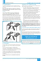
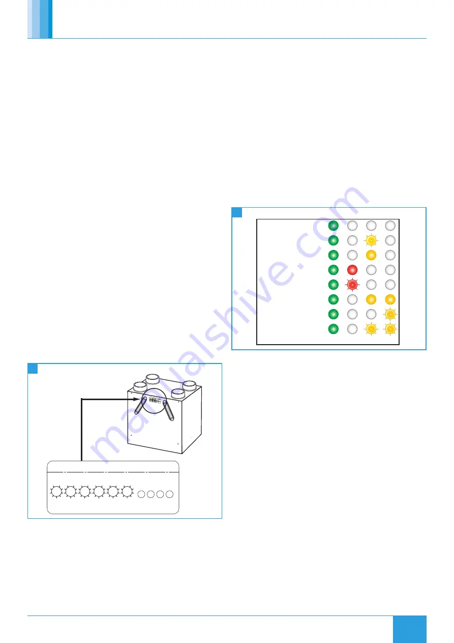
The status of the unit is indicated by a series of LED’s on the front cover.
The variants are listed below.
The display on the unit control panel will not indicate when a
higher speed setting has been triggered by an external source, such
as an ES-PIR2 etc.
19
Unit Control On Front Panel
HX Bypass
(AB units only)
Speed 1
Speed 2
Speed 3
Supply Fan Fault
Extract Fan Fault
Frost Protection
Filter Change
6.3 Integral Automatic HX Bypass
Intake and extract temperatures are monitored at the point the
airflows enter the unit, if the range falls within the set parameters the
bypass damper is opened automatically to target an indoor comfort
temperature all year round.
The extract temperature is an average from all wet rooms. If this
exceeds 25°C the unit may go into bypass depending on outside
temperatures.
6.4 Summer / Winter Switch
When the switch position is set to Summer the integral automatic
summer bypass is fully operational, in the alternative Winter position
the HX bypass is disabled to ensure the unit is constantly in heat
recovery mode.
6.5 Speed 3 Operation (SW Units Only)
Speed 3 will be non-operational if the intake temperature is greater
than the extract temperature.
6.6 Frost Protection
In the event of the intake air temperature at the unit dropping below
the predetermined set point (-5°C as standard) the supply fan will
reduce to minimum speed, once the temperature rises above the set
point the fan will return to its commissioned speed.
Frost protection will only activate after ten days of continuous run
time. If commissioning of the unit is outside of this time frame please
notify the after sales department prior to site visit.

