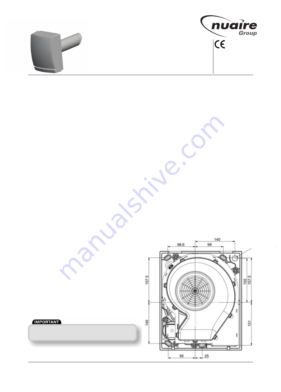
1.0 The Nuaire NA-SRHR-100 Single Room
Heat Recovery Fan
The fan is suitable for refurbishment or new build in Kitchen,
Bathroom and Toilet applications. The fan can be directly installed
into existing 100mm fan holes.
The fan will run continuously at a 6l/s trickle extraction rate with
an automatic boost to 15l/s when activated by the integral
humidistat sensor.
2.0 Where to install the fan
1 In walls 380mm maximum thickness.
2. Locate it as high as possible.
3. At least 100mm from the edges of the mounting surface to
sides/top of unit.
4. As far away as possible from and opposite to the main
source of air replacement to ensure airflow across the room
(e.g. opposite the internal doorway.
5. Near the source of steam or odours.
6. Not where ambient temperatures are likely to exceed 50°C
or are below -20°C.
7. If installed in a kitchen fans must not be mounted immediately
above a cooker hob, or eye level grill.
8. If installing in a room containing a fuel burning device which
has a non-balanced flue, it is the installer's responsibility to
ensure that there is enough replacement air to prevent fumes
being drawn down the flue when the fan is operating up to
maximum extract. Refer to Building Regulations for specific
requirements.
9. Exhaust air must not be discharged into a flue used for
exhausting of fumes from appliances supplied with energy
other than electric. Requirements of all authorities concerned
must be observed for exhaust air discharge and intake flow
rates.
10.Not suitable for use in possible chemical corrosive
atmospheres.
11.Do not site where the fan is exposed to water spray for
extended periods.
3.0 What the installer will need
3mm electrician’s screwdriver and No.1 or 2 Pozidrive screwdrivers.
A 115mm dia. prepared hole with a slope to the outside, cut with a
minimum 115mm dia. core drill.
4.0 Fan Installation
Installation should be carried out by competent personnel in
accordance with the appropriate authority and conforming to
all statutory and governing regulations.
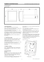
Installing the isolating switch and cable.
l
Isolate the mains supply.
l
Lay in the cable from the isolating switch to the fan location.
l
Lay in the cable from the isolating switch to the point of
connection to the mains supply.
l
Install the isolating switch and make connections required.
Installing in the wall of maximum thickness 380mm.
l
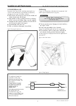
Use the dimensions in fig 1. to mark the wall with the centre
of the duct hole, the 4 wall fixing positions and the cable inlet.
l
Use the centre line to cut a 115mm dia. hole through the wall
for the wall tube using a core drill (if replacing the tube of an
existing 100mm dia. fan ensure the wall tube fits without
distortion.
l
ENSURE THAT THE DUCT SLOPES DOWN, away from the fan at
an angle of 3o to allow drainage of any incoming rain water to
the outside.
l
Drill 4 holes for wall fixings (not supplied), in positions shown
and fit wall plugs. (see fig 1.)
l
Align the fan in the duct hole and ensure the fan wall box fits
flat and flush to the wall.
Nuaire Limited
Western Industrial Estate Caerphilly United Kingdom CF83 1NA
T: 029 2085 8400 F: 029 2085 8444 E: info@nuaire.co.uk W: www.nuaire.co.uk
NA-SRHR-100
Single Room Heat Recovery Fan
Installation and Maintenance
The EMC Directive
2004/108/EC
The Low Voltage
directive
2006/95/EC
Figure 1. Wall fixing positions and cable inlet.
1
27. 04. 15 Leaflet Number 671677
Cable
entry
Centre
line of
duct
Isolation - Before commencing work
make sure that the unit is electrically isolated
from the mains supply.


