background image

2

Leaflet Number 671051 January 2012

Installation and Maintenance

XS Wall Fan Kits

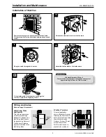
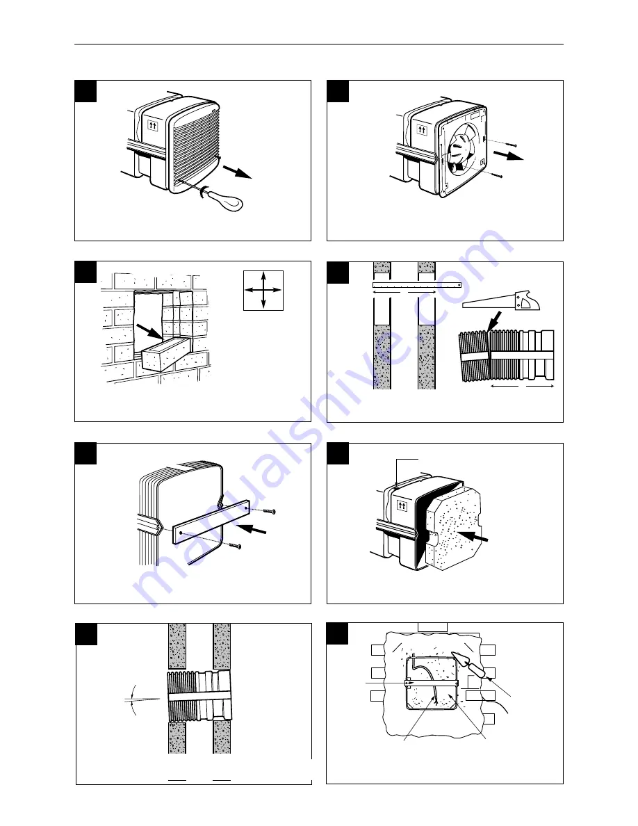
Fit the temporary cross brace across wall sleeve’s outer
end to support the sides during installation (drg No 8).

Polystyrene
former fits
temporarily
into sleeve end

Make hole for 
supply cable

Locate the temporary plug to support the other end.

Polystyrene form er
supporting sleeve
end

Supply w ire
inside sleeve

M ake good
the inside and
outside w alls

ush w ith the 

sleeve

Tem porary
Cross brace

A

A

Install the sleeve
at a slight angle
(lower to outside) 

INSIDE

OUTSIDE

1

2

3

5

4

6

7

8

Remove front grille.
Release 2 screws. Lift grille upwards.

Prepare the wall aperture to dimensions shown. 

Make good around the wall sleeve.

Remove fan plate.

XS6WA  260mm sq.

XS9WA  330mm sq.

XS12WA 410mm 

sq.

IMPORTANT !

Cut the spacer to match the walls  total thickness
using a fine/med cut woodsaw.

When fitting the sleeve, introduce a slight downward slope
to the outside, to encourage any water to drain to outside.

Installation of Wall Fan kits

Summary of Contents for XS6WA

Page 1: ...of the push on impeller for cleaning Upward angled interior grille vanes shield workings from view and downward sloping external vanes throw off rain The fan is IP24 splash proof approved with the mot...

Page 2: ...ood t hei ns i deand out s i dewal l s us h wi t h t he s l eeve Tem por ar y Cr os sbr ace A A Install the sleeve at a slight angle lower to outside INSIDE OUTSIDE 1 2 3 5 4 6 7 8 Remove front grille...

Page 3: ...llaries Also see page 8 for details Wall Fixing Plate and Spacer This thin wall application is best covered using a Window Kit Drg shows a Wall Fixing Plate fixed to the aperture by 4 screws The Windo...

Page 4: ...ied electrician in accordance with the wiring regulations Isolation Before commencing work make sure that the unit is electrically isolated from the mains supply 1 2 3 4 Release the electrical panel f...

Page 5: ...ight Model Watts kg Max Economy XS6WA supply extract 38 20 4 7 Note figures are for extract only Electrical Specification 230V 50Hz Class I Motor thermally protected by overload device Cable 1mm max o...

Page 6: ...cover from the grille Fitting Integral Sensors optional Note Before following the pictorial sequence shown first remove the fans front cover grille 2 screws Release the four main corner screws and li...

Page 7: ...Sensors optional The XS MFC Multi Fan Control provides supply or extract variable speed and automatic or manual switching of several fans if desired see note below The control is best mounted approx 1...

Page 8: ...d with each unit 2 Has not been connected to an unsuitable electrical supply The correct supply voltage is shown on the appliance rating label attached to the unit 3 Has not been modified or repaired...

Reviews: