9
31. 08. 21. Document Number 671746
Nuaire | Western Industrial Estate | Caerphilly | CF83 1NA | nuaire.co.uk
BPS (V/T)-ES
Installation Manual
6.9 Filters
6.9.1 Filter Removal
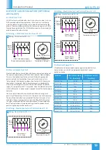
Filters will be provided in banks on suitable slide rails, so that they can
be withdrawn from the access side of the unit. Differential "Dirty Filter"
pressure switches are fitted as standard.
6.9.2 Spare Filters
If specified with order, spare sets of filters will be provided and should
be stored in a clean, dry environment. Should you require spare filter
media, please contact Nuaire.
20
Filter Side Withdrawal
6.10 Control Dampers
Care should be taken to ensure that all spring return actuators have
stopped running and completed their stroke. If not, the connection
needs to be loosened and the actuator should be left to drive until the
motor stops running.
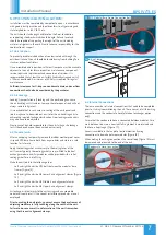
When the unit is powered, dampers should be checked to ensure that
they operate freely and close tightly.
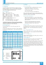
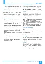
Where dampers are protected with a roof terminal, the roof terminal
can be removed for access to the main damper. Access to the actuator
can be from the side of the roof terminal without the requirement of
removing the roof terminal (Figure 22).
21
Removing Roof Terminal
22
Actuator Access
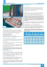
6.11 Damper / Roof Terminal Assembly
The inlet/outlet dampers and roof terminals are pre-assembled (for BPS
sizes
07
,
12
and
17
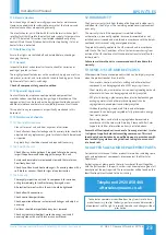
) on a double skinned and insulated panel. The panel
is easily fitted to the unit with a series of quarter turns (provided with a
locking key) (Figure 23).
For the larger size BPS units (
22, 32
and
42
) the pre-assembled
dampers and terminals are provided with lifting eyes for on-site
hoisting into position (Figure 24).
23
Inlet / Outlet Damper / Terminal Quarter Turn Fixings
24
Inlet / Outlet Damper / Terminal Lifting Eyes (22, 32 & 42)
6.12 Supporting Ancillary Items
All ancillary items that are supplied without individual base frames
require safe suitable support (supplied by others). This includes but is
not limited to single attenuators, terminals and dampers etc.
6.13 Installation Inspection
•
Thoroughly inspect the unit after installation is complete.
•
The inside of the unit should be checked; any objects which may
have been left should be cleared.
•
Check fan impellers, scrolls and outlets.
•
Remove any transit protection fittings that may be attached to the
fan or motor base frame, and that all traps are primed.
•
Close all access door seals for damage, and replace any panels that
have been removed.


