background image

Isolation - Before commencing work make sure that 

the unit and Nuaire control are electrically isolated 

from the mains supply.

5.

0 Wiring

Wiring Connections for units with Ecosmart Control.


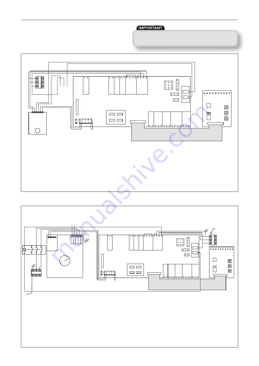
Wiring for units with Electric Heater 3Kw 

Fig 14: 

Wiring for units with Electric Heater 4.5 – 9 Kw 

Fig 15: 

Installation, Operating and Maintenance Instructions

INV

DRIVE

18V

EN2

EN1

0V

0-10V

BK

WHT

RED

0V

0-10V

18V

0V

0-10V

SET

POINT

CO2

IN

BMS

HEAT

SENS

FAULT

RUN

HEAT

DEMAND

DAMPER

OP

CL

N

RET

SUPPLY

N

E

L

SL

Net Ecosmart

P IN

0V

0-10V

Standby

Fan1

Fan 2

Heating

Cooling

Fault

Frost

Tx

Rx

PWR

Min

Max

SL

Run-On

Trickle

0

1

650462 (830109)

Test

Neutral 230V/220V

Live 230V / 220V

Live Load

Neutral Load

Sensor

Sensor

HEATER NEUTRAL

HEATER EARTH

HEATER LIVE

E

N

L

Heater Temperature Settings

INV

DRIVE

EN2

EN1

0V

0-10V

BK

WHT

RED

0V

0-10V

18V

0V

0-10V

SET

POINT

CO2

IN

BMS

HEAT

SENS

FAULT

RUN

HEAT

DEMAND

DAMPER

OP

CL

N

RET

SUPPLY

N

E

L

SL

Net Ecosmart

P IN

0V

0-10V

18V

Standby

Fan1

Fan 2

Heating

Cooling

Fault

Frost

Tx

Rx

PWR

Min

Max

SL

Run-On

Trickle

0

1 650462

(830109)

Test

A1

A2

4T2

3L2

R2

2T1

1L1

6T3

5L3

Heater 
GND

Heater Live

Heater Neutral

Thermistor T Thermistor R

Signal 0V

VE

OIP 5V

Note:

Customer connections
for electric heater.
40amp draw.

E

N L

L

N

E

Heater Temperature Settings

Note:
Customer connections

for fan and control.
5amp draw max.

5

18. 10. 17. Leaflet Number 671679

Notes: Local isolator (by others)
All inter-connections between circuit boards, blowers and sensors are made at the 
factory. Remove link wire if switched live signal, an enabler or BMS signal is connected.

COOL DOWN PROTECTION (ELECTRIC HEATER) NOTE: Ecosmart cool down protection 
is activated if the fan is disabled whilst the electric heater is enabled. The unit reacts by 
running the fan for a cool down period of 10 minutes; this allows any residual heat left by 
the operation of the electric heater to dissipate

 safely

.

DAVE Supply Fans (ES Models) 50/60Hz

Summary of Contents for DAVE Series

Page 1: ... are manufactured from aluzinc rectangular in section and have circular rigid spigots at each end All units are supplied with fixing brackets designed to simplify installation 1 0 Fan Unit Coding Descriptions 2 0 Handling Always handle the units carefully to avoid damage and distortion Care must be taken to ensure any slings used for hoisting do not damage the casing or the control module componen...

Page 2: ...5 190 DS3A EES H 1005 780 345 200 430 155 155 DS4A NES H 1005 840 370 250 370 150 100 DS4A LES H 1005 840 370 250 430 175 190 DS4A EES H 1005 840 370 250 430 155 155 DS4HA NES H 1005 840 370 250 370 150 100 DS4HA LES H 1005 840 370 250 430 175 190 DS4HA EES H 1005 840 370 250 430 155 155 DS5A NES H 1155 1110 1110 984 410 315 370 150 100 DS5A LES H 1155 984 410 315 430 175 190 DS5A EES H 1155 984 4...

Page 3: ...valve to a fully open position to allow full water flow through the coil and the main PCB will close the Heat demand contacts These contacts could be used to send a signal to activate the boiler and or valve to open to provide heat if not already doing so 4 1 2 Port Pressure Independent Balancing Control Valve Setting Instruction Fig 6 Remove Actuator Fig 7 Unlock Adjusting Collar Units 1 2 2H DN2...

Page 4: ...el details Note A Commissioning Procedure document leaflet No 671153 is available on request from Nuaire Tel 029 2088 5911 The Control Module Fig 12 The BMS connection is made with a plug in connector via the socket See figure 13 To ensure the connection is made only by suitably qualified and authorised personnel the plug is not supplied It is available from R S Components Part No 403 875 or Farne...

Page 5: ...ater Neutral Thermistor T Thermistor R Signal 0V Signal VE OIP 5V Note Customer connections for electric heater 40amp draw E N L L N E Heater Temperature Settings Note Customer connections for fan and control 5amp draw max 5 18 10 17 Leaflet Number 671679 Notes Local isolator by others All inter connections between circuit boards blowers and sensors are made at the factory Remove link wire if swit...

Page 6: ...OL COOLING CONTROL 0V SETPOINT 0 10V 10V 0V DEADBAND 0 10V 10V AUTO HEAT COOL OFF ON COOL SENSOR ACTUATOR CONTROL WHITE ACTUATOR CONTROL BLACK ACTUATOR CONTROL RED Note Customer connections for fan and control 5amp draw max 6 18 10 17 Leaflet Number 671679 Notes Local isolator by others All inter connections between circuit boards blowers and sensors are made at the factory Remove link wire if swi...

Page 7: ...nce Ensure all control components are secure and clean refit the cover Lubrication Motors are fitted with sealed for life bearings and do not require any lubrication Filter care replacement The filter where applicable will require cleaning on a regular basis The frequency of the cleaning operation will depend on the site conditions 7 0 Fan Components see fig 18 Key Components A Lid Base B Attenuat...

Page 8: ...es office for further details 9 0 Spares for Dave Supply fans Spare parts and replacement components are available from Nuaire Ltd Please contact us on the numbers below for further details G4 Filter Unit Size Replacement Part No DS1A ES D1A G4FILTERKIT DS2A ES D2A G4FILTERKIT DS2HA ES D2HA G4FILTERKIT DS3A ES D3A G4FILTERKIT DS4A ES D3A G4FILTERKIT DS4HA ES D4HA G4FILTERKIT DS5A ES D5A G4FILTERKI...

Page 9: ...nged so as not to bear on the casing 3 3 Equipment stored on site prior to installation should be protected from the weather and steps taken to prevent ingress of contaminants 4 0 OPERATIONAL LIMITS 4 1 It is important that the specified operational limits for the equipment are adhered to e g operational air temperature air borne contaminants and unit orientation 4 2 Where installation accessories...

Reviews: