Isolation - Before commencing work make sure that
the unit and Nuaire control are electrically isolated
from the mains supply.
5
.0 Wiring
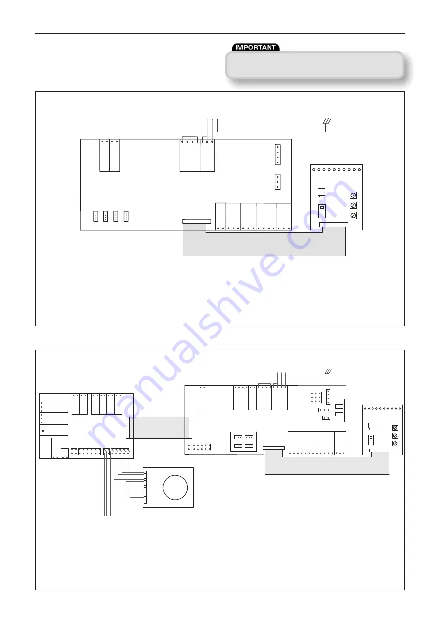
Wiring Connections for units with Ecosmart Control.
Wiring for units with No Heater
Fig 16:
Wiring for units with LPHW
Fig 17:
Installation, Operating and Maintenance Instructions
Standby
Fan1
Fan 2
Heating
Cooling
Fault
Frost
Tx
Rx
PWR
Min
Max
SL
Run-On
Trickle
0
1
650462
(830109)
Test
P IN
E
V I
R
D
V
N
I
0V
0-10V
18V
EN2
EN1
0V
0-10V
BK
WHT
RED
0V
0-10V
18V
0V
0-10V
T
E
S
T
N
I
O
P
N
I 2
O
C
BMS
FAULT
RUN
DAMPER
OP
CL
N
RET
SUPPLY
N
L
SL
Note:
Customer connections
for fan and control.
5amp draw max.
INV DRIVE
EN2
EN1
0V
0-10V
BK
WHT
RED
0V
0-10V
18V
0V
0-10V
SET POINT
CO2 IN
BMS
HEAT SENS
FAULT
RUN
HEAT DEMAND
DAMPER
OP
CL
N
RET
SUPPLY
N
E
L
SL
Net Ecosmart
P IN
0V
0-10V
18V
Standby
Fan1
Fan 2
Heating
Cooling
Fault
Frost
Tx
Rx
PWR
Min
Max
SL
Run-On
Trickle
0
1 650462 (830109)
Test
1
2
3
4
5
6
7
8
9
10
11
12
13
14
24v
24v
O/P 1
O/P 1
O/P 1
T8109C
T8109C
Honeywell
T8078C
DX
COIL
COOL
DEMAND
DX-1
FROST ALARM
DX-2
INLET
SENSOR
OUTLET
SENSOR
HEATING CONTROLCOOLING CONTROL
0V
SETPOINT0-10V
10V
0V
DEADBAND
0-10V
10V
AUTO
HEAT/COOL
OFF
ON
COOL
SENSOR
ACTUATOR CONTROL (WHITE)
ACTUATOR CONTROL (BLACK)
ACTUATOR CONTROL (RED)
Note:
Customer connections
for fan and control.
5amp draw max.
6
18. 10. 17. Leaflet Number 671679
Notes: Local isolator (by others)
All inter-connections between circuit boards, blowers and sensors are made at the factory.
Remove link wire if switched live signal, an enabler or BMS signal is connected.
Notes: Local isolator (by others)
All inter-connections between circuit boards, blowers and sensors are made at the factory.
Remove link wire if switched live signal, an enabler or BMS signal is connected.
FROST PROTECTION (LPHW) NOTE:
Ecosmart frost protection is activated when the outlet
air of the unit is 4
o
C or below, when this temperature is reached, the unit reacts by shutting
down the fan to prevent a ‘wind chill’ effect reducing the temperature to a point whereby
the coil could freeze and burst. The unit will also drive open the LPHW valve to a fully open
position to allow full water flow through the coil and the main PCB will close the ‘Heat
demand’ contacts. These contacts could be used to send a signal to activate the boiler and/
or valve to open to provide heat if not already doing so.
DAVE Supply Fans (ES Models) 50/60Hz


