


2
10. 05. 17. Leaflet number 671174
Installation and Maintenance
AIRMOVER Supply & Extract Fans
Warning - Inverter Speed Control
An Inverter is used to provide speed control. When the fan is
isolated, allow 5 minutes for the capacitors in the inverter
to discharge before commencing any work on the unit.
4.0 Getting Started
The Ecosmart Airmover fan is designed for maximum
control flexibility. The control should be supplied from a
local isolation (by others) and the control connected to
the fan by screened cable and suitable glands.
(maximum length 30m).
Apart from the power supply an enabling signal is always
required to set the fan running. This can be a switched time
signal (connect to SL) or an enabling device plugged in the
net connection. If an enabling signal is not available, connect
a link wire from ‘L’ to ‘SL’.
Note: the unit must be fused in
line with the full load current on the fan rating label.
4.1 Ecosmart Compatible Devices
Enabling Devices
ES-PIR:
PIR Sensor
ES-TC:
7 Day Timeclock
Sensors
ES-TEMP:
Temperature Sensor ES-CO2
ES-RH:
Humidity Sensor
User Controls
ES-UCF:
Fan Only Control
Others
ES-JB:
Junction Box (to add extra sensors etc)
ES-AVI:
Audio Visual Fault Control
Note: these Ecosmart devices will affect all the fans linked
using the SELV data cable. The switched live signal will only
affect the fan to which it is connected.
4.2 Control Connections
Net
- the 4 IDC plug-in connectors are provided for the
connection of compatible sensors, manual controls and for
linking the fans together under a common control. If more
than 4 connections are required, the junction box (product
code ES-JB) should be used (see ‘data cable installation’
below).
Switch Live (SL) terminal - A signal of 100-230V ac will
activate the fan.
Note that a signal from an isolating
transformer will produce unpredictable result and is not
recommended.
4.3 Volt Free Relay Controls
Note that the volt free contacts are not fused. If these are
used to power any external equipment, the installer must
provide adequate fusing or other protections.
These contacts are rated at 5A resistive, 0.5A inductive.
Run connections - These contacts are closed when the fan
is running.
Fault connections - No fault = the contacts are closed.
Fault = the contacts are opened (this includes no power
supply at the unit)
4.4 Data Cable Installation
A 4-core SELV data cable is used to connect devices such
as sensors to the fan and interconnecting multiple fan units.
Do not run data cable in the same conduit as the mains
cables and ensure there is a 50mm separation between the
data cable and other cables. The maximum cable run
between any two devices is 300m when it is installed in
accordance with the instructions.
Please note that the total data cable length used in any
system must be less than 1000m. Keep the number of cable
joints to a minimum to ensure the best data transmission
efficiency between devices.
4.5 Maximum number of devices
The maximum number of devices (including fans) that can
be connected together via the cable is 32, irrespective of
their functions. Any other low voltage/signal cable connection
i.e. BMS follow the guidelines as given in ‘“Data Cable” and
keep the cable length as short as possible - less than 50m.
4.6 Settings
Setting the maximum air flow
ii) Ensure the power supply is switched off and that a link
wire is connected from the supply L to the SL terminal.
Unplug all items connected to the ‘Net‘ connectors.
ii) Switch on the power supply.
iii) Wait for the fan to complete its self-test operation.
Measure the airflow using standard commissioning
instruments at a suitable point in the ductwork.
If adjustment is required, rotate the pot marked ‘MAX’ to
obtain the desired airflow.
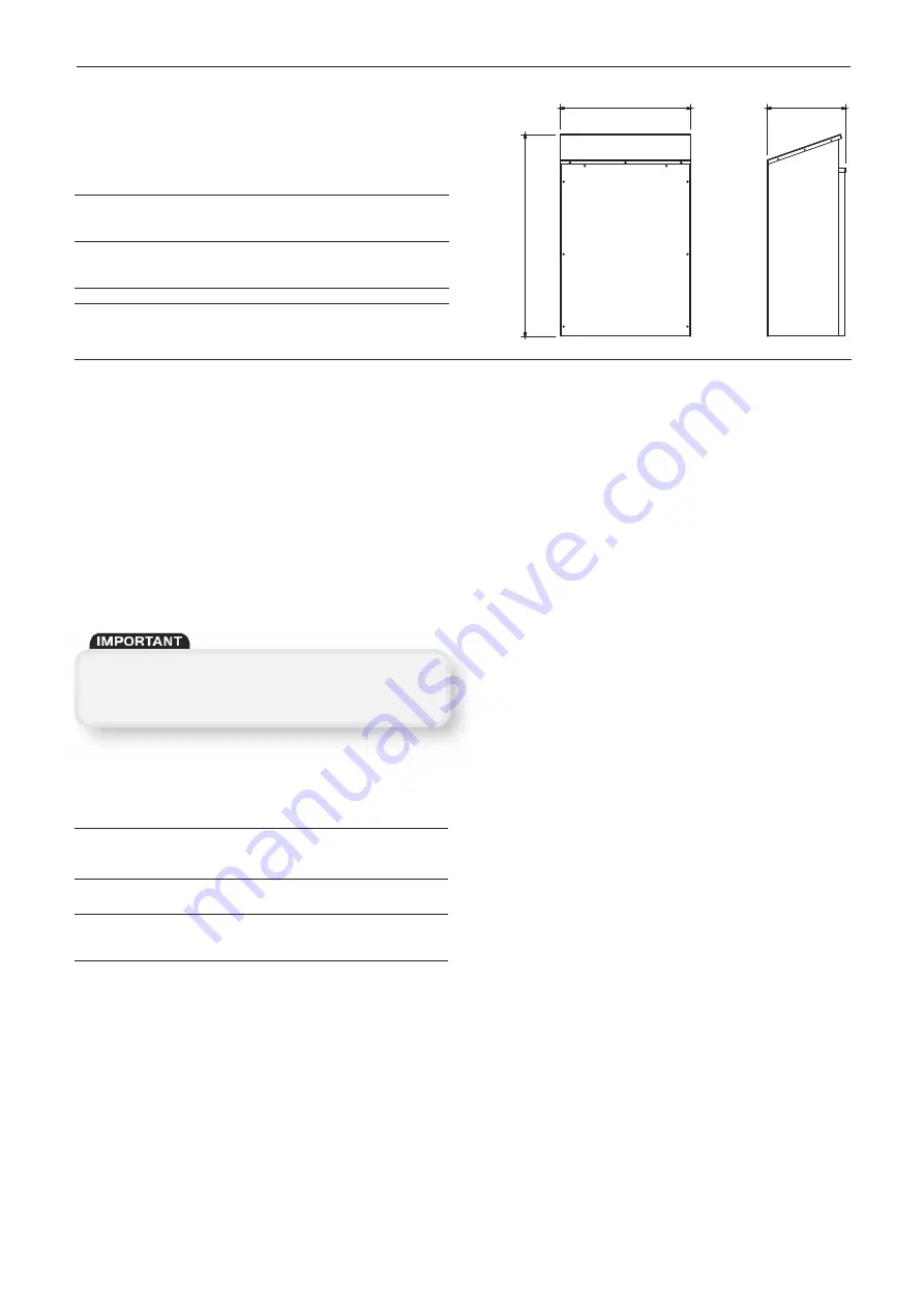
Compatible
Cover Code
A
B
C
Models
Airmover
ES-ISC-WPA
626.2
476.8
286.6
1.2-4.1
AM21, AM22,
AM41, AM42,
AM43
ES-ISC-WPB
687.5
559.3
343.1
5.6-23.1
AM23, AM24,
AM44, AM45,
AM61, AM62
ES-ISC-WPC
1069.1
691.3
415.3
26-Above AM46
3.0 Outdoor Weather Covers Coding
and Dimensions
A
B
C
Figure 4.


