4
10. 05. 17. Leaflet number 671174
Installation and Maintenance
AIRMOVER Supply & Extract Fans
5.1 Wiring Connections
400v 3ph 50Hz
Switch live signal
N L1 L2 L3
Connections
to damper
Ribbon cable
to commission box
Volt free
contact
RUN signal
R
un F
ault
Ecosmar
t N
e
t
Volt free
contact
FAULT signal
5A resistive
0.5 A inductive
N
L
SL
OP
CL
NET connections
for Ecosmart devices
No user
Connection
CO2
Connection
0 -10V signal
from BMS
Remove this link wire if
a switched live signal is
connected to terminal SL
Note: also remove link if
a BMS system is connected
Also remove link if an enabling
device is connect in the NET
MIN
=
MAX
=
SL Run on =
TRICKLE
=
TEST
=
LED indicators
Min Max SL run on
Trickle
Test
0 1
Pwr
Standby
Fan 1
Fan 2
Heating
Cooling
Fault
Frost
Tx
Rx
Minimum speed
adjustment
Maximum speed
adjustment
Switched Live Run-On
Timer adjustment
Selects trickle running:
0 = off, 1 = selected
Test button
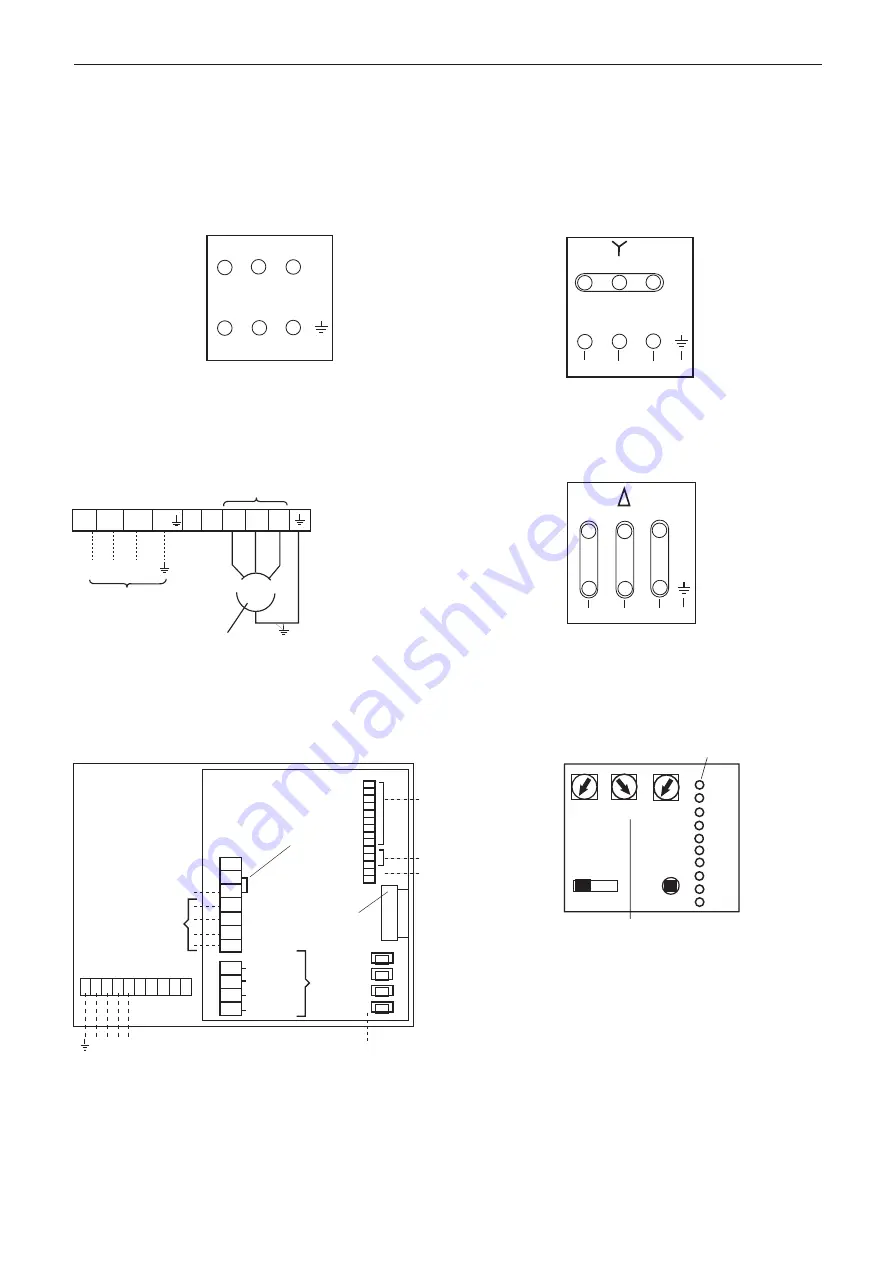
3 phase (Ecosmart)
Two speed motors DOL starting on both speeds
3 phase units up to 3KW
3 phase units with matched frequency inverter
3 phase units 4KW and above
Set up/Commissioning Box
3 phase motors are connected directly to the Motor
Terminal Box.
Observe the motor plate and connection details.
3 phase two speed tap/pam wound motors require a three
contactor control.
3 phase Dual wound motors require a two contactor
control.
V1
W1
L
V2
U1 V1
W1
L1
L2
L3
E
W2 U2
V2
S
2
1V
1W
2
E
4
W1
V1
W1
L
E
W
V2
U V1
W1
L
E
W
V2
C
S
2
1V
1W
2
E
4
U
W2
L1
U2
L2
V2
L3 E
U1
V1
W1
W1
L
E
W
V2
U V1
W1
L
E
W
V2
C
S
2
1U 1V
1W
2U
2V
2W
E
400V 3 phase 50Hz supply
V1
W1
Motor Terminal Box
Note: HIGH SPEED -
Supply 2U 2V 2W
Link 1U 1V 1W
LOW SPEED
Supply 1U 1V 1W
N
V1
W1
L
V2
U V1
W1
L
E
W
V2
C
S
2
1W
2
L1 L2 L3
L1 L/L2 N/L3 PE/
W V
U
400V 3 phase 50Hz supply
3 Phase only
INVERTER SPEED CONTROL
Connect as figure 7 or 8.
Connections
to motor
3 Phase input
Ecosmart
3 phase
W1
Notes:
If screened motor cable is
used, the maximum length
should be 30m.
Consult our Technical
Department if you wish to
use longer leads.
Inverters are configured to
suit specific fans and
control applications as
described on the Customer
Order.