


2.7 ADF 2010 Ventilation Calculations
Design of MVHR Systems
The MVHR system has been sized for the winter period. Additional
ventilation may be required during the warmer months and it has
been assumed that the provisions for purge ventilation (e.g. openable
windows) could be used.
Step 1:
For any design air permeability, determine the whole dwelling
ventilation supply rate
from Table 2.
As an alternative where the design air permeability is intended to be
leakier than (>) 5m
3
/(h.m
2
) 50 Pa, allow for infiltration for all
dwelling types by subtracting from the whole dwelling ventilation
supply rate
from Table 2
; 0.04 x gross internal volume of the dwelling
heated space (m
3
).
Step 2:
Calculate the whole dwelling extract ventilation rate by
summing the individual room rates for ‘minimum high rate’
from
Table 1.
(For sanitary accommmodation only, as an alternative, the purge
ventilation provisions given in ADF 2010 can be used where security
is not an issue. In this case ‘minimum high extract rate’ for the
sanitary accommodation should be omitted from the step 2
calculation).
Step 3:
The required airflow rates are as follows:
n
the maximum whole dwelling extract ventilation rate (e.g. boost)
should be at least the greater of step 1 and step 2.
Note that the maximum individual room extract rate should be
at least those given
in table 1.
for minimum high rate.
n
the minimum air supply rate should be at least the whole building
ventilation rate found in step 1.
For Scotland refer to BRE Digest 398.
For further information refer to “Domestic Ventilation Compliance
Guide” www.planningportal.gov.uk/buildingregulations/approved
documents/partl/compliance
4
27. 11. 17. Leaflet Number 671721
Installation and Maintenance
The WH1 Wall Mounted Range of Units
11
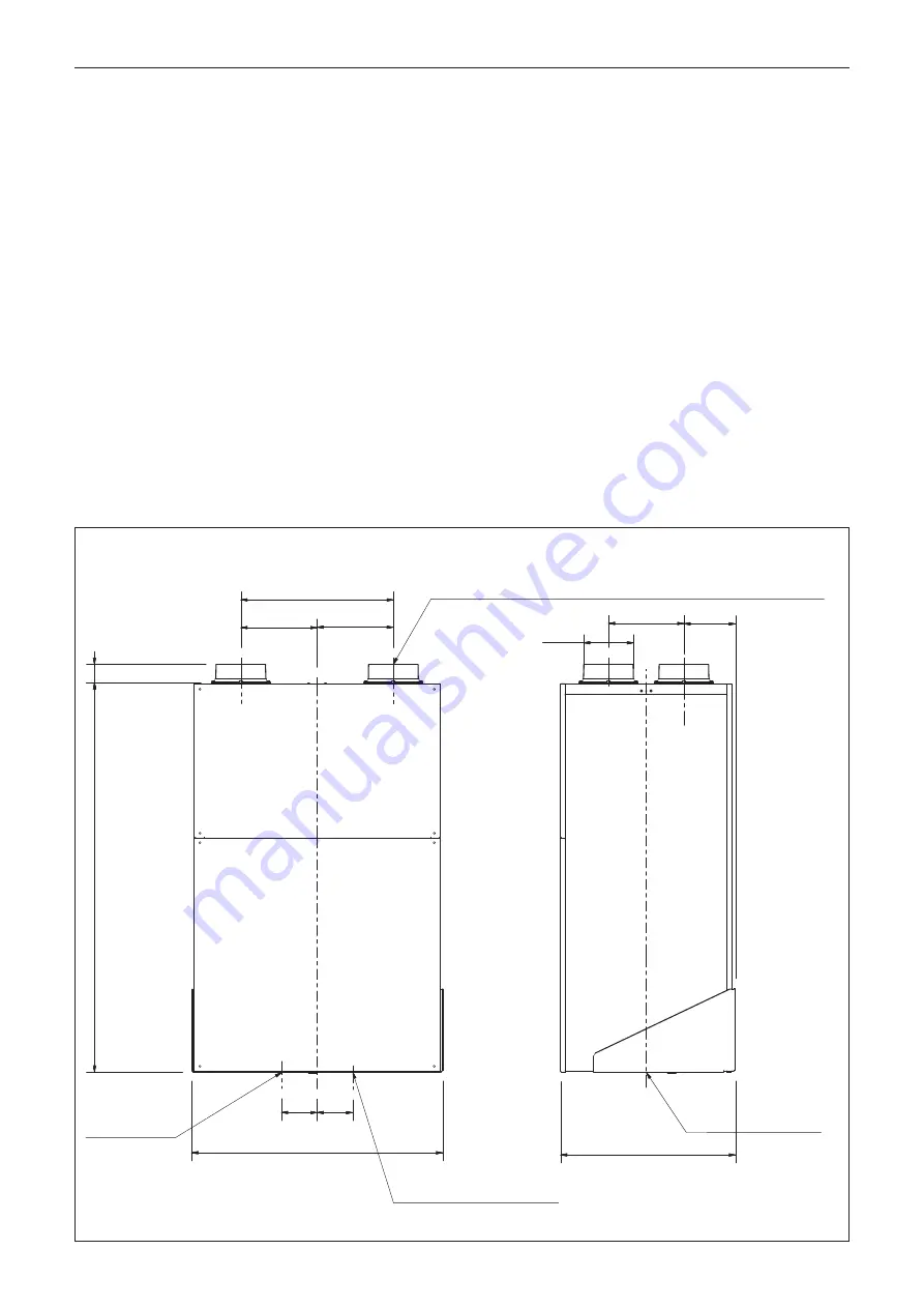
69
754
525
55
227 CR S
155
458 CRS
=
=
107
UNI T WEI GHT = 76Kg
CONDENSATE DRAIN CONNECTION
(OPPOSITE HAND CONFIGURATION)
107
150.0
Ø
Condensate drain
connection
(standard
configuration)
Condensate drain
connection
on centre line
of unit
if ancillary distribution box (DB-WH1) is to be used refer to documentation
supplied with DB-WH1 for additional infomation as requirements will differ.
Condensate drain connection
(opposite hand configuration)
3.0 Dimensions
Figure 9.


