background image

5

27. 11. 17. Leaflet Number 671721

Installation and Maintenance

The WH1 Wall Mounted Range of Units

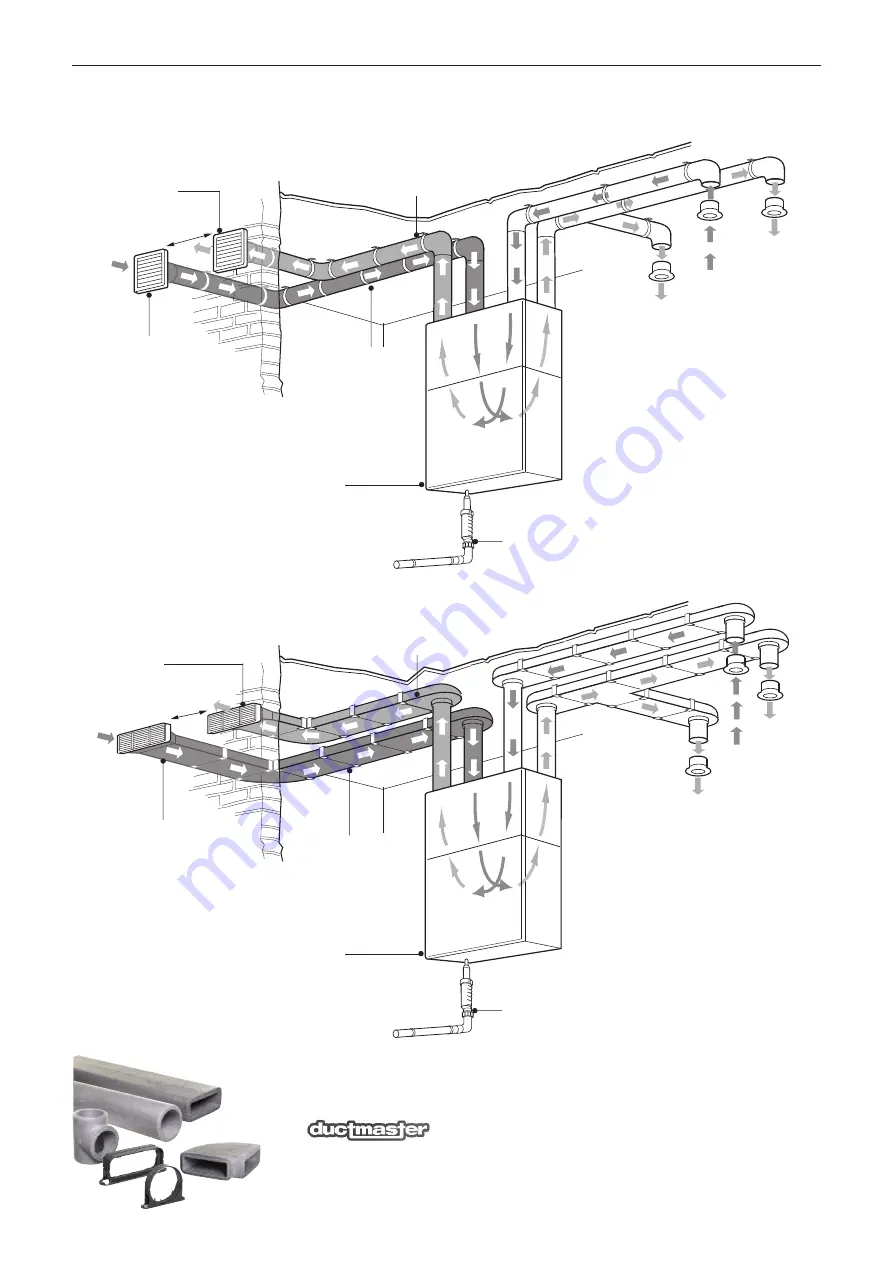
4.0 Ducting Arrangements - Standard Configuration 

Air supply 
to lounge 
via Air Valve 
in ceilings.

Extract air 
from 
kitchen/
bathroom 
via Air Valve 
in ceilings.

Minimum distance as specified 
in building regulations.

Exhaust air from 
kitchen/bathroom to 
outside via louvre grille.

Intake air 
from outside
via louvre grille.

All duct between MVHR 
unit and atmosphere to 
be insulated*.

Exhaust air from 
kitchen/bathroom to 
outside via air brick.

Intake air 
from outside
via air brick.

All duct between MVHR 
unit and atmosphere to 
be insulated*.

*Insulated 
supply duct.

*Insulated 
supply duct.

Air supply  
to lounge 
via Air Valve 
in ceilings.

Extract 
air from 
kitchen/
bathroom 
via Air Valve 
in ceilings.

Air supply 
to bedrooms 
via Air Valve
in ceilings.

Top of ceiling void.

Top of ceiling void.

Air supply to 
bedrooms 
via Air Valve 
in ceilings.

*Insulated 
extract duct.

*Insulated 
extract duct.

Minimum distance as specified 
in building regulations.

MVHR-DRAIN
Condensate drain, uninsulated 
drain pipe with min 5

o

 fall running to SVP.

Nuaire wall 
mounted unit.

MVHR-DRAIN
Condensate drain, uninsulated 
drain pipe with min 5

o

 fall running to SVP.

Nuaire wall 
mounted unit.

Figure 10a. Typical ducted arrangement for a wall mounted unit using circular ducting.

Figure 10b. Typical ducted arrangement for a wall mounted unit using rectangular ducting.

ALSO FROM NUAIRE - 

New

range of thermal ducting,

an all-in-one insulated ducting system. 

(see installation document 671620).

Summary of Contents for Ecosmart MRXBOX95-WH1-1Z

Page 1: ...opriate authority and conforming to all statutory governing regulations All mains wiring must be in accordance with the current I E E Regulations or the appropriate standards Ensure that the mains supply Voltage Frequency and Phase complies with the rating label Please allow a minimum of 430mm in front of the enclosure for MRXBOX95 WH1 models and 360mm for MRXBOX95AB WH1 units The fan must be inst...

Page 2: ...nd the cover plate slid along the length to bond against the base panel of the enclosure preventing noise breakout fig 7 Figure 7 1 The condensate must be discharged under a water level in a U trap drainpipe or an alternative drain method which acts as an airlock 2 If using a U trap please ensure the U trap has been filled to a suitable level of water to avoid any air locks 3 If the condensation p...

Page 3: ...et duct and the air outlet duct from the unit these ducts should be insulated Ducting must be installed in such a way that resistance to airflow is minimised Bends should be kept to a minimum A minimum distance of 300mm between the appliance and any bends in ductwork is recommended Ideally 150mm diameter or 220 x 90mm rectangular ducting should be used Refer to dwelling design drawing figure 10a a...

Page 4: ...sanitary accommodation should be omitted from the step 2 calculation Step 3 The required airflow rates are as follows n the maximum whole dwelling extract ventilation rate e g boost should be at least the greater of step 1 and step 2 Note that the maximum individual room extract rate should be at least those given in table 1 for minimum high rate n the minimum air supply rate should be at least th...

Page 5: ...pply duct Air supply to lounge via Air Valve in ceilings Extract air from kitchen bathroom via Air Valve in ceilings Air supply to bedrooms via Air Valve in ceilings Top of ceiling void Top of ceiling void Air supply to bedrooms via Air Valve in ceilings Insulated extract duct Insulated extract duct Minimum distance as specified in building regulations MVHR DRAIN Condensate drain uninsulated drain...

Page 6: ...ion to Remote Fail Indicator Ref MRXBOX95 RFI Optional 3 2 Figure 11a Note Wiring is for reference purposes only as the connections in fig 11a are factory fitted The unit is pre wired with a 2 metre fly lead Disconnection from the supply mains must be incorporated within the fixed wiring in accordance with the wiring regulations and shall have a minimum contact separation of 3mm Disconnection from...

Page 7: ...l covering the control has an adhesive panel which should be removed post commissioning to prevent tampering 8 Speed 1 is limited to never exceed the speed 2 when commissioning the speed 2 should always be set first 6 1 Speed 3 The unit has to ability to override both speed 1 and speed 2 to operate the fan to maximum airflow See wiring diagram for details of operating this facility 6 2 Humidity ad...

Page 8: ...arranty The 5 year warranty starts from the day of delivery and includes parts and labour for the first year and parts only for the remaining 4 years This warranty is void if the equipment is modified without authorisation is incorrectly applied misused disassembled or not installed commissioned and maintained in accordance with the details contained in this manual and general good practice The pr...

Reviews: