


14
08. 06. 18. Leaflet Number 671408
Installation, Operating and Maintenance Instructions
SQURBO XBOX
fins. Do not probe the coil fin block with metal objects as damage
may cause leaks.
Drain lines should be checked to ensure that they are unobstructed
and free draining. Traps should be checked that they are fully
primed and functioning.
Drain pans should be flushed out periodically to remove
contamination.
Note: The unit application may require particular attention to
this item – Check with Building Management personnel for
details.
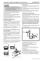
6.4 Electric Heaters
Electric heaters should be checked at regular intervals for condition
of elements, wiring and insulation.
6.5 Recuperator
The recuperator block is normally protected from dust and
contamination by upstream pre-filters. It is possible to clean the
unit with compressed air in the case of dust deposits or by spraying
with a mild detergent solution for grease deposits.
Solvents, strong alkaline, acidic or any products that may be
aggressive to aluminium should not be used. Do not use cleaning
water over 50 deg C.
Drain lines should be checked to ensure that they are unobstructed
and free draining. Traps should be checked that they are fully
primed and functioning.
Drain pans should be flushed out periodically to remove
contamination, and chemical treatments may be used to provide
protection between service visits.
Note: The unit application may require particular attention to
this item – Check with Building Management personnel for
details.
6.6 Fans, Motors and Belt Drives
Fan bearings should be manually checked at regular intervals for
condition. Standard fan bearings are supplied as ‘sealed for life’
and have an anticipated life of 40,000 hours.
Motors have an enclosed bearing housing and are pre-greased for
life. Belts should be checked for wear, tension and alignment.
Check all fixings are secure.
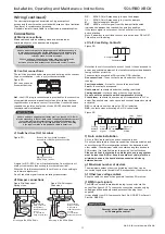
Checking drive belt Tension (Sizes 9 & 10)
To check the correct tension of a drive belt, apply a force at right
angles to the centre of the belt span sufficient to deflect the belt
16mm for every metre of span length.
The force required to deflect the ‘V’ belt should be from 0.5kg to
0.8kg.
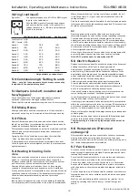
Changing a drive belt
To replace a belt, remove the two bolts from the motor mounting
furthest from the fan and slacken the remaining two bolts.
Lift the motor plate and remove the belt. Replacing the belt is the
reverse of this procedure.
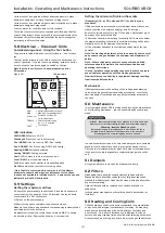
Adjusting drive belt tension
All belt drive units incorporate a belt tensioning facility.
To adjust the belt tension, slacken the pinch bolts on the sides of
the motor plate. Use the motor platform pivot adjustment to
tighten and loosen the belt.
Clean impellers with a soft brush only, and remove dust/deposits
from all internal surfaces including the motor housing,
6.7 General
Inspect all internal and external surfaces to check for corrosion or
peeling of painted surfaces.
Thoroughly clean affected areas with a wire brush, apply a coat
of zinc rich primer or similar, and re-touch with suitable finishing
paint. Ensure tightness of all nuts, bolts, and fixings.
Check all components for general condition.
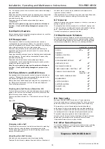
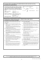
7.0 Maintenance
Schedule
The first maintenance should be carried out three months after
commissioning and thereafter at six to twelve monthly intervals.
These intervals may need to be shortened if the unit is operating
in adverse environmental conditions, or in heavily polluted air.
6 MONTHS
12 MONTHS
FILTERS
4
or
4
DAMPERS
4
DAMPER ACTUATORS
4
BELT DRIVES
4
FILTER MANOMETER FLUID
4
VENT WATER COILS
4
COIL FINNED SURFACES
4
CHECK DRAIN LINES + DRIP TRAY
4
4
CLEAN & FLUSH DRAIN PANS
Building
Schedule ?
4
NUTS, BOLTS, FIXINGS SECURE
4
FAN BEARINGS
4
ELECTRIC HEATERS
4
ELECTRICAL WIRING
4
FAN IMPELLER
4
GENERAL
4
8.0 Warranty
Ecosmart SQURBO XBOX units have a 5 year warranty.
No control units have a 2 year warranty. The first year covers
parts and labour and the remaining period covers parts only.
This warranty is void if the equipment is modified without
authorisation, is incorrectly applied, misused, disassembled, or
not installed, commissioned and maintained in accordance with
the details contained in this manual and general good practice.
The product warranty applies to the UK mainland and in
accordance with Clause 14 of our Conditions of Sale. Customers
purchasing from outside of the UK should contact Nuaire
International Sales office for further details.
9.0 After Sales Enquiries
For technical assistance or further product information, including
spare parts and replacement components, please contact the
After Sales Department.
Telephone 02920
858
400
Figure 36:


