C
ONT
A
CT
OR
Connections
to Damper
F
A
UL
T R
UN
N
L
SL
DP
CL
N
RET
Remove this link wire if:
1. a switched live signal is connected.
2. A ES-PIR, ES-TC or BMS signal
is connected.
NET connections for
ECOSMART devices
Min Max SL run on
Trickle
Test
0 1
Pwr
Standby
Fan 1
Fan 2
Heating
Cooling
Fault
Frost
Tx
Rx
Ecosmart
Heat demand
signal
Earth
Run signal
Fault signal
HEA
T
D
AMPER
DEMAND
L3
L2
L1
N
E
400V 50Hz
3ph +N mains
1 3 5
2 4 6
(U)
(V) (W)
L1 L2 L3 E
(U)
(V) (W)
L3
L2
L1
12 13 14 15
5 6 7 8 9
10 11
C
ONT
A
CT
OR
A1
A2
0V
0-10V
BMS signal
12 13 14 15
SUPPLY 1
7
08. 06. 18. Leaflet Number 671408
Installation, Operating and Maintenance Instructions
SQURBO XBOX
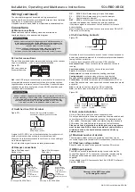
Unit sizes S7 - S10 Extract fan - all versions and unit sizes S7 - S10 Supply fan without heater
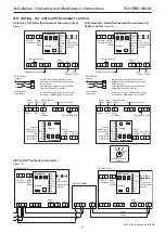
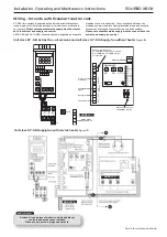
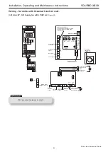
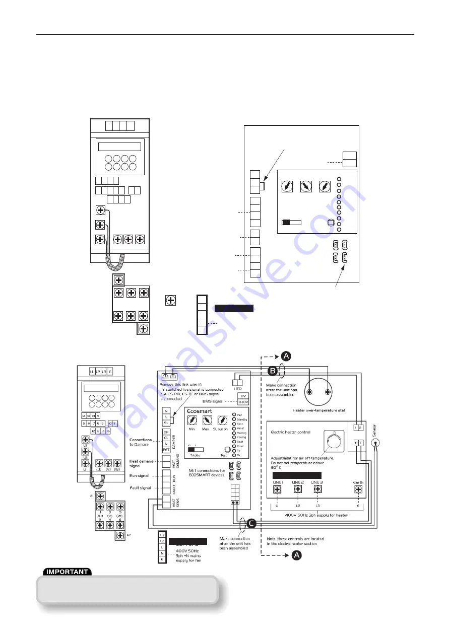
Figure 18:
Unit sizes S7 - S8 Supply fan with electric heater
Figure 19:
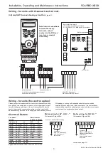
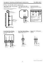
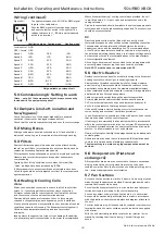
Wiring - for units with Ecosmart control cont.
S7-XBV: this variant is supplied with all modules bolted together
into a single unit. All wirings between the modules are pre-wired in
our factory.
Please note separate mains supply must be connect-
ed to the extract and supply fan control.
S8-10 XBV and S7-10 XBH: these variants are supplied as separate
modules for on site assembly. The connections between the
modules are pre-wired into clearly identified plugs and sockets;
these must be plugged together during on-site assembly.
Please note separate mains supply must be connected to the
extract and supply fan control.
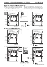
SUPPLY 1.
Section A is an adjacent module in which additional
controls and sensors are installed.
These are pre-wired to plugs and sockets.
SUPPLY 3.
SUPPLY 2.


