
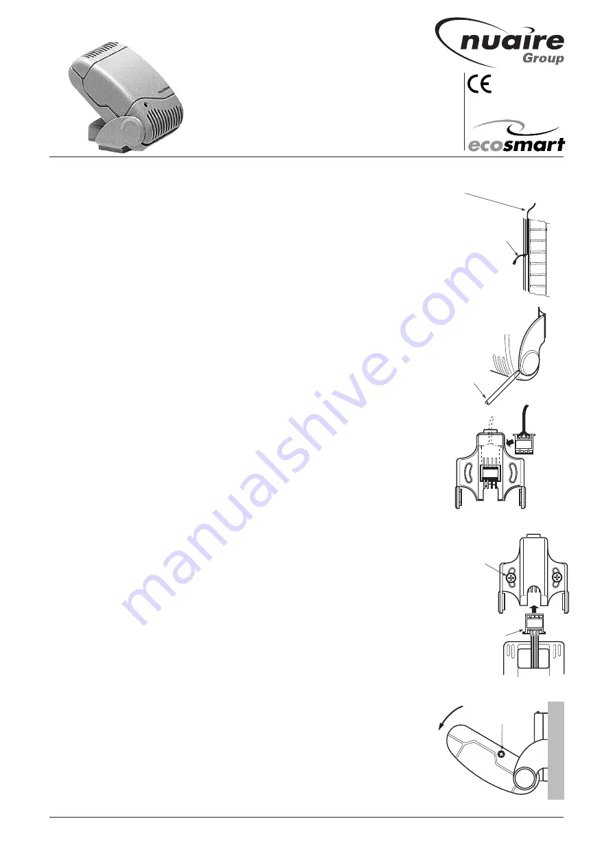
Set point
adjuster screw
Small screwdriver
Note colour
code guide
label when
fitting
Backplate
(rear view)
10m sensor connection
wire (supplied).
Clearance aperture for wire
should be approx 20mm dia
to allow passage of plug end.
Allow approx 75mm of wire
through for fitting to the
backplate
Wire can be located behind
a wall panel or fixed to wall
surface.
Plug end
Before fixing the backplate
to the wall, fit the plug end
from sensor body into the
backplate.
Note that colour coded
connections are matching
Sensor can now clip onto
backplate
Wall
To fan connector
box terminal
marked NET
Fixing screws supplied
IMPORTANT! Please refer to the
installation instructions of the fan to
check the compatibility of this sensor.
Parts check list:
l
ES-TEMP Temperature Sensor
l
1 off 10 metre length of plugged
SELV cable
ES-TEMP Temperature Sensor
Designed to be compatible with the Ecosmart
system, this temperature sensor unit is
supplied with a pre-plugged, 10 metre length
of communications cable.
Note: longer
lengths are available if required.
The sensor operates with Safe Extra Low
Voltage (SELV) with power supplied from
the fan unit via the communications cable.
The ES-TEMP Sensor will vary the ventilation
rate automatically according to the
measured temperature.
Fault indication
The LED will change from green to red if
any fan connected in that zone has failed.
Multiple Sensors
Multiple sensors can be connected to the
network. Please refer to the actual fan
installation instructions for exact
quantities.
Installing the Sensor
The sensor unit should be installed away
from any direct source of heat (e.g.
radiators) and areas where it would be
subjected to waterspray.
The Sensor is supplied complete with
10 metres of connecting cable with plugs
attached. Sensors are also supplied with all
fixings and are clipped into a backplate wall
mounting bracket.
a) Fix one end of the 10m cable to the fans
customer connection box (connection
sockets marked NET).
b) Select a suitable location for the sensor
and arrange the cable in position. Leave
approx. 75mm of the cable free at the
mounting point to ease the connection
of the plug. (fig. 1).
c) Carefully separate the sensor from the
backplate using a small screwdriver
(see Fig 2)
Note: the sensor will remain
connected by its internal cable.
d) Release this cable from the bracket by
simply pulling the plug off the socket pins
in the backplate.
e) Before fixing the backplate to the wall,
connect the wall fixed cable end plug to
the upper set of pins on the bracket (fig 3)
N
ote: check the colour code matching
on
when fitting the plug onto the pins.
Arrange the cable to lay in the cable slot
at the top of the backplate moulding and
fix the bracket to the wall surface using
the screws supplied.
f) The sensor plug can now be connected
into the backplate N
ote: check the colour
code matching
when fitting the plug onto
the pins.
Clip the sensor body in the backplate arms
and adjust the sensor body to the desired
position.
Data cable installation
A 4-core SELV data cable is used to
connect devices.
Do not run data cable in the same conduit
as the mains cables and ensure there is a
50mm separation between the data cable
and other cables. The maximum cable run
between any two devices is 300m when it
is installed in accordance with the
instructions.
Please note that the total data cable length
used in any system must be less than
1000m. Keep the number of cable joints to
a minimum to ensure the best data
transmission efficiency between devices.
Adjusting the sensor set points
Adjustable temperature setting 10 -35
o
C
Assuming the sensor(s) are installed,
adjustment of the set points achieved by
tilting the sensor forwards which exposes
the adjustment aperture (see fig 5).
Using a small screwdriver, gently turn the
dial either clockwise or anti-clockwise to
increase or decrease the set point.
When adjustments are made to the sensor,
the LED light on the sensor front will flash
on and off to show the set point. First,
green flashes will indicate the set point in
TENS, then red flashes will indicate UNITS.
For example 2 green flashes and three
red flashes show a temperature set point
of 23
o
C.
ES-TEMP
Temperature Sensors
Installation Guide
Figure 1.
Figure 2.
Figure 3.
Figure 4.
Figure 5.
Nuaire Limited
Western Industrial Estate Caerphilly United Kingdom CF83 1NA
T: 029 2085 8400 F: 029 2085 8444 E: info@nuaire.co.uk W: www.nuaire.co.uk
03. 07. 15. Leaflet Number 671128
The EMC Directive
2004/108/EC
The Low Voltage
directive
2006/95/EC


