10
nuaire.co.uk
029 2085 8400
13. 03. 19. Document Number 671188
Installation and Maintenance
Ecosmart Boxer Air Handling Units
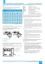
The system’s response to a 0-10V dc BMS signal is given in the table
below.
Note the BMS signal will override any sensors and user control
connected in the system. The voltage tolerance is +/- 125mV and is
measured at the fans terminal.
*Only available on relevant unit.
Ventilation
Mode
Cooling
Mode*
Heating
Mode*
Local Control
0.00
-
-
OFF/ Trickle
0.25
-
-
Speed 1
0.50
0.75
1.00
Speed 2
1.50
1.75
2.00
Speed 3
2.50
2.75
3.00
Speed 4
3.50
3.75
4.00
Speed 5
4.50
4.75
5.00
Speed 6
5.50
5.75
6.00
Speed 7
6.50
6.75
7.00
Speed 8
7.50
7.75
8.00
Speed 9
8.50
8.75
9.00
Speed 10
9.50
9.75
10.00
4.1.10 LPHW Actuator Connections
LPHW actuator connection (unit sizes 3-7) must be made between the
control and LPHW modules, using link wire provided.
Note: Actuator wiring can change dependent on direction of
operation (Figure 23 & Figure 24).
Direction
of Operation
Direction
of Operation
WHITE
BROWN
GREEN
WHITE
BROWN
GREEN
BLU
BRN
BLU
BRN
BLK
BLK
Figure 23.
Figure 25.
Figure 24.
5.0 Setting to Work
5.1 Electrical
5.1.1 Test Button
The test button allows the blower within the unit to be checked for its
operation. If the fan is running already, press the button once to stop
the fan, press again to switch on the fan.
Note that the fan will return to normal operation after 30 seconds.
MIN
MAX
= Minimum speed adjustment
= Maximum speed
LED indicators
Max SL run on
Min
adjustment SL
Run on = Switched Live Run-On
Timer adjustment
TRICKLE = Selects trickle running:
0 = off, 1 = selected
TEST
= Test button
Trickle
Test
1
0
Pwr
Standby
Fan 1
Fan 2
Heating
Cooling
Fault
Frost
Tx
Rx
Ecosmart
Connector
5.1.2 LED Indication (Figure 25)
PWR
GREEN: Power on & OK.
STANDBY
LED on when fan is not running.
FAN 1
GREEN: Fan 1 is running, RED: Fan 1 faulty.
FAN 2
GREEN: Fan 2 is running, RED: Fan 2 faulty.
HEATING*
GREEN: Heating selected
COOLING*
Not applicable, see note.
Fault
LED on when a fault is present on unit.
Frost*
Not applicable, see note.
Tx
LED on when the controller is transmitting data.
Rx
LED on when the controller is receiving data.
*Note that the control panel is common to all the Ecosmart products
and will have indicators for functions that are not available in this
particular fan. However these indicators will not be illuminated.
5.1.3 Maximum Airflow Rate
•
Ensure the power supply is switched off and that a link wire is
connected from the supply L to the SL terminal. Unplug all items
connected to the ‘Net’ connectors.
•
Switch on the power supply.
•
Wait for the fan to complete its self-test operation. Measure the
airflow using standard commissioning instruments at a suitable
point in the ductwork. If adjustment is required, rotate the pot
marked ‘MAX’ to obtain the desired airflow. Remove the link wire if
not required - see “wiring (c)”.
5.1.4 Maximum/Trickle Airflow Rate (Nominal: 40% Sizes 1 & 2;
20% Sizes 3 to 7)
•
Repeat the same procedure as for maximum airflow above but
without the link wire between supply L and SL terminal. Ensure the
trickle switch is in the ‘ON’ position. Adjustment must be made on
the pot marked ‘Min’.
•
Note that the minimum setting (nominally 40%) must be
below the maximum setting, or the minimum setting will be
automatically set to be the same as the maximum.
•
The minimum speed set is the trickle speed at which the fan
operates.
Note: The working speed range of the user control and sensors is
between the minimum and maximum set points.
5.2 Mechanical
•
Wet systems require the setting of the flow valve. Set as general
commissioning procedures - refer to the specified design flow
duties and the documentation attached to each valve.
•
Frost protection must be incorporated on shut down and
fresh air conditions to avoid the coil and associated pipework
freezing. Ideally, where the system is at risk of frost damage,
the addition of a proprietary antifreeze solution to the water is
recommended.
•
DX coils have two separate cooling stages with independent
condenser units, the coils are supplied with ends sealed.
Connection, commissioning and setting to work is the
responsibility of the condensing unit installer


