6
nuaire.co.uk
029 2085 8400
13. 03. 19. Document Number 671188
Installation and Maintenance
Ecosmart Boxer Air Handling Units
Connections
to Damper
N
L
SL
DP
CL
N
RET
Remove this link wire if:
NET connections for
ECOSMART devices
1. a switched live signal is connected.
2. A ES-PIR, ES-TC or BMS signal
is connected.
Max SL run on
Min
Trickle
Test
1
0
Pwr
Standby
Fan 1
Fan 2
Heating
Cooling
Fault
Frost
Tx
Rx
Ecosmart
Heat demand
signal
Earth
Run signal
Fault signal
DAMPER
FAULT RUN
HEAT DEMAND
L3
L2
L1
N
E
400V 50Hz
3ph +N mains
5
3
6
1
2 4
(U)
(V) (W)
E
L3
L2
L1
L3
(U)
(V) (W)
L2
L1
15
14
13
12
9
8
7
6
5
11
10
15
12 13 14
CONTACTER
A1
A2
0V
0-10V
BMS signal
Connections
to Damper
N
L
SL
DP
CL
N
RET
Remove this link wire if:
NET connections for
ECOSMART devices
1. a switched live signal is connected.
2. A ES-PIR, ES-TC or BMS signal
is connected.
Max SL run on
Min
Trickle
Test
1
0
Pwr
Standby
Fan 1
Fan 2
Heating
Cooling
Fault
Frost
Tx
Rx
Ecosmart
signal
Heat demand
Run signal
Fault signal
DAMPER
FAULT RUN
HEAT
DEMAND
L3
L2
L1
N
E
400V 50Hz
3ph +N mains
supply for fan
5
6
3
1
4
2
(U)
(V) (W)
E
L1 L2 L3
(U)
(V) (W)
L3
L2
L1
15
13
12
14
9
6
5
8
7
10 11
15
13 14
12
CONTACTER
A1
A2
2
Electric heater control
1
LINE 1
LINE 3
Earth
LINE 2
Adjustment for air off temperature.
Do not set temperature above
30°C
L3
L2
L1
E
400V 50Hz 3ph supply for heater
Note: these controls are located
in the electric heater section
HTR
Heater over-temperature stat
Make connection
after the unit has
been assembled
0V
0-10V
BMS signal
Make connection
been assembled
after the unit has
T
R
Sensor
HEAT
SENS
A
B
A
B
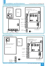
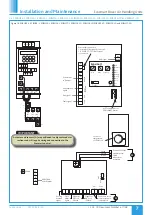
Figure 12. ESBHEX3, ESBHEX4, ESBHEX5, ESBHEX6 and ESBHEX7.
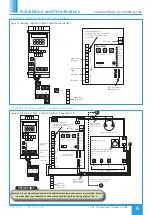
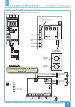
Figure 13. ESBHS3-E, ESBHS4-E, ESBHS5-E, ESBHS6-E and ESBHS7-E.
IMPORTANT
Section A is an adjacent module in which additional controls and sensors are installed. Ensure
these devices are connected to the Ecosmart control by terminating at points B & C.
4.2.5 ESBHEX3, ESBHEX4, ESBHEX5, ESBHEX6 and ESBHEX7
4.2.6 ESBHS3-E, ESBHS4-E, ESBHS5-E, ESBHS6-E and ESBHS7-E


