2
029 2085 8400
23. 06. 17. Leaflet Number 670901
Installation and Maintenance
FLAT2000L/R Low Energy Positive Input Ventilation Unit
Points to consider
•
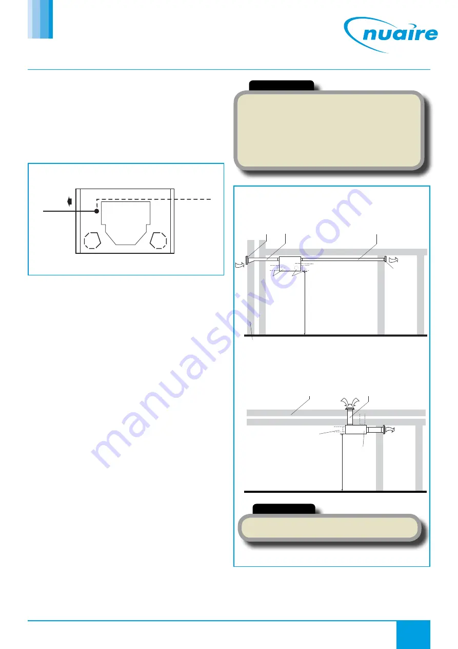
The inlet ducting should be kept as short as possible to avoid condensation
build up on the ducting surface (see fig. 5 and 6).
•
Find the shortest, most direct route from outside of the unit and then to
the discharge grille using the least number of bends (these bends increase
the airflow resistance).
•
Note the location of any joists, pipes, electrical cables etc.
•
Allow adequate access to the front cover to allow filter cleaning.
2.3 Fitting of ducts
To prevent access to live or moving parts ensure ducts are adequately
secured to the spigots by fitting self tapping screws or by other means
requiring a tool. If using duct tape ensure tape cannot be removed
without the use of a tool by securing with tie wraps.
2.2 Fixing the unit to the wall
The unit has three mounting feet. Mark through these feet when
the unit is in the correct position. Drill and plug wall with suitable
fixings. Remove PCB cover and feed the electrical supply cable
through the grommet hole (standard 1mm three core lighting cable is
recommended) in the rear of the unit screw unit to wall (see fig. 3).
Installers must ensure the grommet provided or other suitable
insulated grommet/bushing is used for cable entry.
Supply
cable
position
Supply
cable
optional
position
AIRFLOW
Right Hand Discharge
(when viewed from front)
Figure 3. Supply cable must be secured by passing RH or LH of unit
to clamp cable to the wall (Rear view of unit shown).
2.4 Inlet/Outlet grille installation
If a fly screen is fitted it should be removed from both the internal and
external grille.
NOTE: When installing the internal grille, the louvres
must slant
upwards
to ensure the correct air circulation and the avoidance of
unpleasant down draughts.
The outside wall input grille louvres
must slant downwards
.
Standard 100mm dia ducting or 121 x 60mm ducting is used to connect
the Flatmaster to the input and discharge grilles.
Fixing all necessary ducting
A full range of ductwork and ductwork ancillaries are available. Please
contact Nuaire for further details.
IMPORTANT
Any air intake terminal MUST be installed in accordance with the
appropriate regulation.
As a guide, the BS5440 series of British Standards deals with this issue
and currently states that an air intake must be at a minimum distance
of 300mm from a gas boiler balanced flue. Installers are advised to be
aware of the requirements of this standard when installing ‘through
the wall’ supply air ducting. Similarly, supply and extract air grilles
should be at least 300mm apart.
Alternative
spigot positions
(inlet only)
FLATMASTER
FLATMASTER
Note alternative
inlet spigot positions
Input grille
(louvres slant
downwards)
100mm dia / 121x60mm
rectangular ducting
(note input side kept
as short as possible)
100mm dia / 121x60mm rectangular ducting
Outside wall
Room
(typical)
Hallway
(typical)
Discharge
grille (note
louvres
slant
upwards)
Outside wall
Hallway
(typical)
Air input 100mm dia ducting
Air
discharge
Minimum
height 1.8m
Minimum
height 1.8m
Figure 4. Side input installation.
Figure 5. Rear input installation (view from above).
IMPORTANT
The internal grille must not be placed within 1.5m of a smoke
alarm.


