2
11. 02. 20. Document Number 671382
Nuaire |
Western Industrial Estate
|
Caerphilly
|
CF83 1NA
|
nuaire.co.uk
MEVDC
Installation Manual
1.2 Important Information
This manual contains important information on the safe and
appropriate assembly, transport, commissioning, operation,
maintenance, disassembly and simple troubleshooting of the product.
While the product has been manufactured according to the accepted
rules of current technology, there is still a danger of personal injury or
damage to equipment if the following general safety instructions and
the warnings contained in these instructions are not complied with.
•
Read these instructions completely and thoroughly before
working with the product.
•
Keep these instructions in a location where they are accessible
to all users at all times.
•
Always include the operating instructions when you pass the
product on to third parties.
1.3 Personal Protective Equipment
The following minimum Personal Protective Equipment (PPE) is
recommended when interacting with Nuaire product:
•
Protective Steel Toed Shoes -
when handling heavy objects.
•
Full Finger Gloves (Marigold PU800 or equivalent) -
when
handling sheet metal components.
•
Semi Fingerless Gloves (Marigold PU3000 3DO or equivalent)
- when conducting light work on the unit requiring tactile
dexterity.
•
Safety Glasses
- when conducting any cleaning/cutting operation
or exchanging filters.
•
Reusable Half Mask Respirators
- when replacing filters which
have been in contact with normal room or environmental air.
Nuaire would always recommend a site specific risk assessment by a
competent person to determine if any additional PPE is required.
2.0 INTRODUCTION
Nuaire's MEV-DC units are designed to provide continuous mechanical
extract ventilation to homes in accordance with Part F of the Building
Regulation 2006 & BRE digest 398.
The case is constructed in grey /blue ABS plastic. The full length access
cover which is located on the underside of the unit, on the opposite
side to the mounting bracket, is retained by four 1⁄4 turn fasteners.
This cover is acoustically lined with flame retardant acoustic foam (full
lining also available).
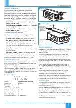
2.1 Code Description:
MEV DC - ES R G2 L H D4
| | | | | | | |
1 2 3 4 5 6 7 8
1. Range:
Mechanical Extract Ventilation
2. Motor Type:
DC Motors
3. Ecosmart Compatibility:
ES
(optional)
4. Run-On Timer (optional):
R
5. Filtration (optional):
G2 or G4
6. Case Lining (optional):
L
7. Humidistat (optional):
H
8. Damper Kits (optional):
S1, S2, D3 or D4
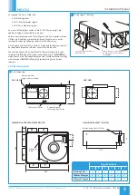
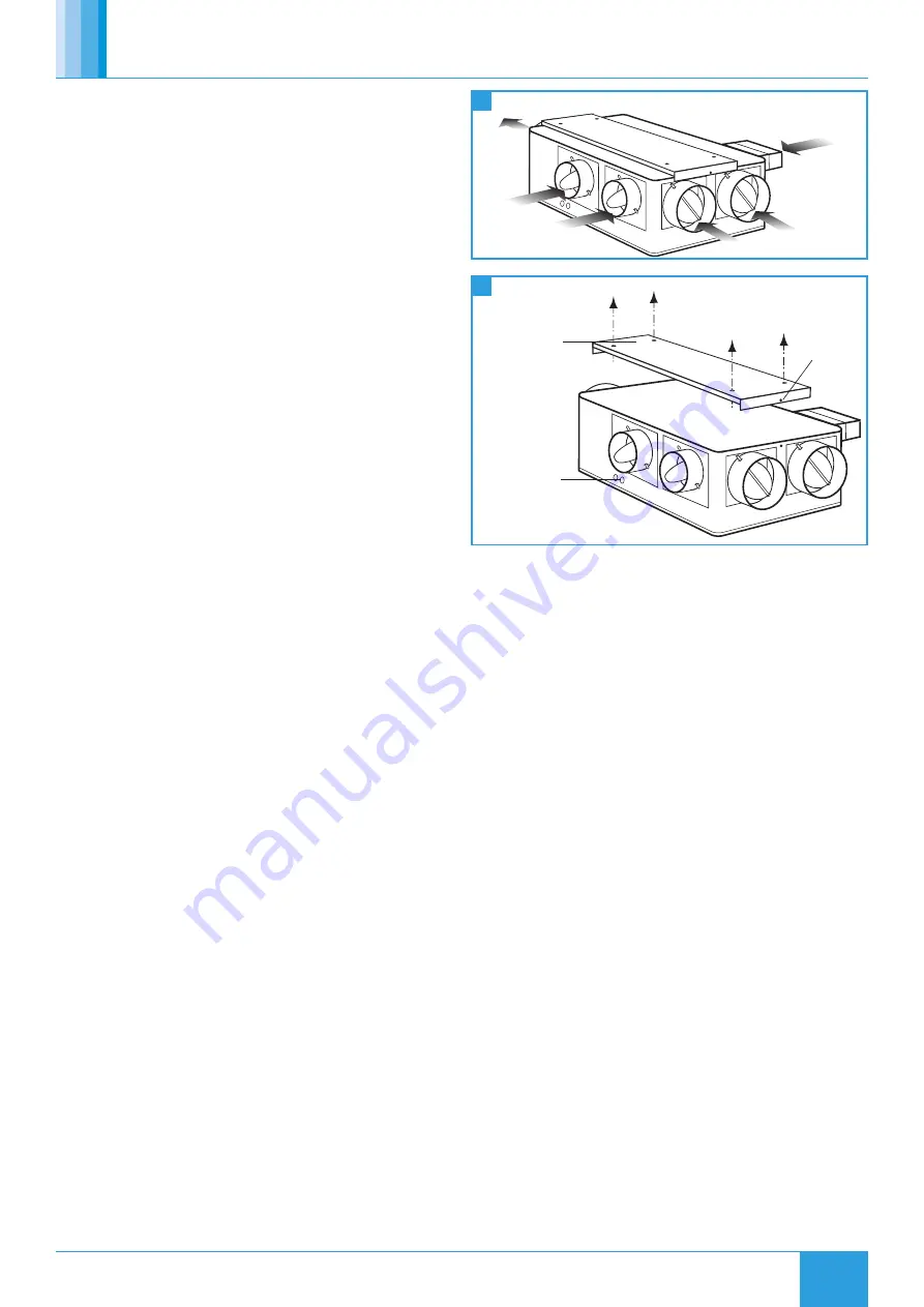
hole.
Fixing screw
Bracket tongues
engage with casing
slots, then unit
rotated up to
align with fixing
screw hole.
2 rubber cable
entry grommets
either side of casing
for external wiring.
1
2
Unit Airflow Path
Unit Mounting Bracket
3.0 INSTALLATION
Installation must be carried out by competent personnel in accordance
with the appropriate authority and conforming to all statutory and
governing regulations.
The fan must be fitted indoors, away from sources of water spray
or steam generation. The fan can be installed at any angle using the
integral mounting bracket supplied (figure 2).
It is assumed that a solid non-reverberant mounting position has been
selected and the electrical mains wiring and any optional control wires
have been made ready.
It is also assumed that compatible ductwork is already installed and
ready to be connected to the 125mm diameter discharge spigot and the
chosen 100mm, 125mm diameter and/or 110 x 54mm rectangular inlet
spigots.
The unit is not fitted with a backdraught shutter (when using the
continuous background vent facility a shutter is not needed). However
a backdraught shutter is available from Nuaire if required.
An integral fixing bracket with a single bolt fixing allows easy mounting
and removal of the unit when necessary. The unit is supplied with the
125mm diameter discharge spigot for fitting during installation.
3.1 Unit Installation
The integral mounting bracket supplied can be offered up to position,
the fixing points marked through and the bracket installed with 4
screws by others (figure 2).
Offer the unit into position and locate the bracket into the slots in the
case before fixing with the single bracket fixing screw.
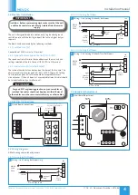
Various damper/inlet spigot positions can be utilised as required to
suit the system ductwork and extract grilles as all spigot positions are
removable.
After the spigots have been located in their correct position, adjust the
damper with a screwdriver (figure 4).


