


3
11. 02. 20. Document Number 671382
Nuaire |
Western Industrial Estate
|
Caerphilly
|
CF83 1NA
|
nuaire.co.uk
MEVDC
Installation Manual
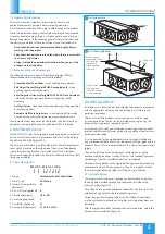
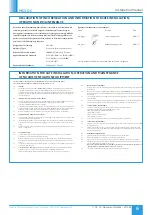
Spigots and spigot blanks are
easily removed.
Spigots dampers can be adjusted to
the appropriate position using a
screwdriver.
As supplied the unit is fitted with:
•
5 off blanking plates.
•
4 off 100mm diameter spigots.
•
2 off 125mm diameter spigots.
Any, or all of the spigots can be utilised. 110 x 54mm spigots plus
additional spigots are available on request.
Volume control dampers and filters (figure 3 and 5) are optional extras.
If filters are fitted they are located inside the fan case and is easily
removed for cleaning following removal of the filter cover.
A clear space of at least 470 x 320mm is required to allow the cover to
be removed and provide sufficient access for maintenance.
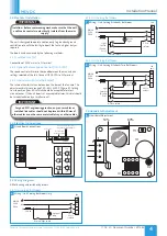
The fan is designed to be wired direct to the mains supply through a
fused spur isolator (by others) and run continuously in the
NORMAL
mode (which is the low speed, background or trickle ventilation setting)
with occasional
BOOST
airflow (high speed setting) as and when
required.
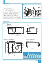
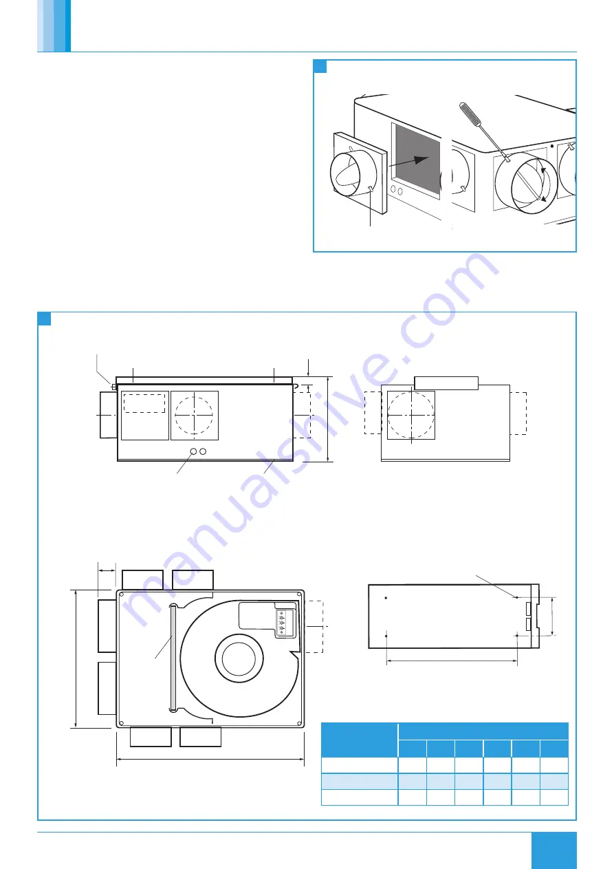
3.2 Dimensions (mm)
3
Fitting spigots / dampers
490
350
331
Bracket fixing 4 holes 7.5 dia.
SIDE VIEW
VIEW WITH ACCESS PANEL REMOVED
Cable entry 20mm
MOUNTING BRACKET TOP VIEW
END VIEW
200
10
50
Mounting bracket
Single screw unit fixing
Removable panel
containing filter access
Optional
filter
80
A
B
F
E
C
D
4
Unit Dimensions
Spigot Positions
A
B
C
D
E
F
Blanking Plates
100mm Ø Spigot
125mm Ø Spigot


