

4
11. 02. 20. Document Number 671382
Nuaire |
Western Industrial Estate
|
Caerphilly
|
CF83 1NA
|
nuaire.co.uk
MEVDC
Installation Manual
3.3 Electrical Installation
IMPORTANT
Isolation - Before commencing work make sure that the unit,
and Nuaire control are electrically isolated from the mains
supply.
IMPORTANT
For good EMC engineering practice, any sensor cables or
switched live cables should not be placed within 50mm of
other cables or on the same metal cable tray as other cables.
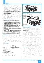
The unit is designed to operate continuously to give a background
ventilation rate with the facility to boost the fan to a higher duty as
required.
The boost can be achieved by the following methods:
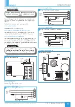
3.3.1 Switched Live (SL)
Connection of 230V mains to SL terminal.
3.3.2 Optional Remote Speed Control (OPUS-SPD)
The speed control will mimic the speed between the max and min
settings selected at the fan. Connect OPUS-SPD to LV terminal.
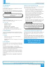
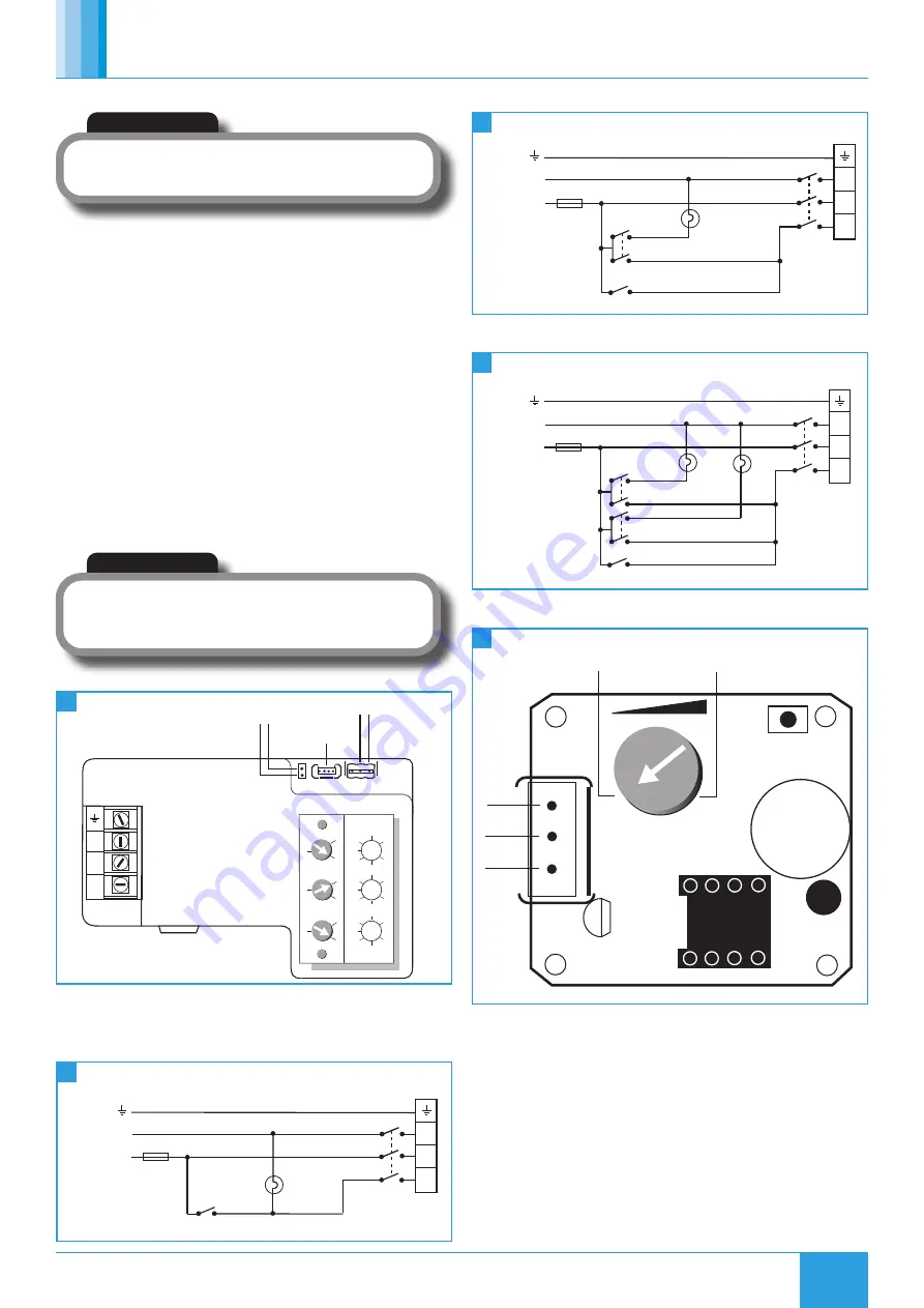
3.3.3 Internal Humidistat (where fitted)
The internal humidistat can be found on the base of the fan case. The
adjustment dial gives a range of 50 - 80% @ 20°C (figure 9). Setting
to mid position gives 65% which should be acceptable for most
circumstances. If the unit boosts at unacceptable times, this dial should
be turned clockwise by a small amount.
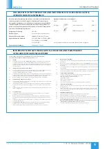
3.5.3 Unit Serving Bathroom
3.6 Humidistat Adjustment
3.5.2 Unit Serving Bathroom
N
L
SL
Do not use
To OPUS-SPD speed control /
Integral Humidity adjustment
To remote fail
indicator ES-AVI2
TEST
Status
30
0
60
Run-on
(mins)
50
10
90
Max
Airflow
(%)
50
10
90
Min
Airflow
(%)
Fuse 2A
Optional
lamp
N
MAINS
230V
50Hz
L
SL
N
L
Fan
Unit
3 Pole
isolator
Remote/light switch
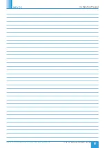
Fuse 2A
MAINS
230V
50Hz
Room
lights
Light
Switches
(Double
Pole)
N
L
SL
N
L
Fan
unit
isolator
3 Pole
Kitchen switch
D2
U1
J1
H1
TH1
50%
80%
Fuse 2A
MAINS
230V
50Hz
Room
light
Light
switch
(Double
Pole)
N
L
SL
N
L
Fan
unit
3 Pole
isolator
Kitchen switch
5
6
8
9
7
Circuit Board Connections
Wiring - Unit Serving Bathroom Only.
Wiring - Unit Serving Kitchen & Two Bathrooms.
Humidistat Adjustment
Wiring - Unit Serving Kitchen & Bathroom.
3.4 Electrical Connections
3.5 Wiring Diagrams
All field wiring and switches by others.
3.5.1 Unit Serving Bathroom


