background image

7

Leaflet Number 671366 July 2007

covers the mounting plate of wall transmitter but not the entire frame.

The use of single-sided decor film (can be purchased from a home-

improvement store) cut to fit the frame size is recommended for

mounting on glass walls. To avoid air bubbles, the decor film should

first be affixed to the glass surface and then the wall transmitter

should affixed using the double-sided adhesive mounting film.

Demounting:

Remove the rocker, release the intermediate frame from the snap 

fits on the top and bottom.

Transmission Range:

The following figures for expected transmission range may be used 

as a rough guide only:

• Line-of-sight connections: 30m range in corridors, up to 

100m in halls

• Plasterboard and dry wood: 30m range, through max. 5 walls

• Bricks and aerated concrete: 20m range, through max. 3 walls

• Ferroconcrete : 10m range, through max. 1 ceiling

Fire-safety walls, elevator shafts, staircases and supply areas should

be considered as screening.

Restriction of transmission range:

• Switch mounted on metal surfaces, or in metal frames (up to 

30% loss of transmission range)

• Hollow lightweight walls filled with insulating wool on metal foil

• False ceilings with panels of metal or carbon fiber

• Lead glass or glass with metal coating, steel furniture

The distance between receivers and other transmitting devices such

as computers, audio and video equipment that also emit high-

frequency signals should be at least 0.5m

5.6 Initialising (also see 6.3)

The mrXbox90S is fitted with a pressure-controlled filter indication

and frost control. For optimum performance of these features we

recommend you initialise the unit. This will ensure that the system

pressure as function of the quantity is recorded in the memory.

After initialisation, the unit will automatically become operational

again.

Always put the mechanical switch in position 1 (= check mode) for 

initialising.

It is important that after initialisation no more changes are made in

the duct system. For that reason, any dampers, grilles and valves

must be installed and adjusted prior to initialisation. In addition, the

unit must be fitted with new, clean filters.

Also remember to switch off any other fans linked to the same duct

system.

6.0 Switching the unit on and off

There are two methods to switch the unit on or off.

1.  Standby mode; the unit remains connected to the 

mains, when switching off only the fans are stopped.

2.  Removing the mains lead from the power supply.

Switching on

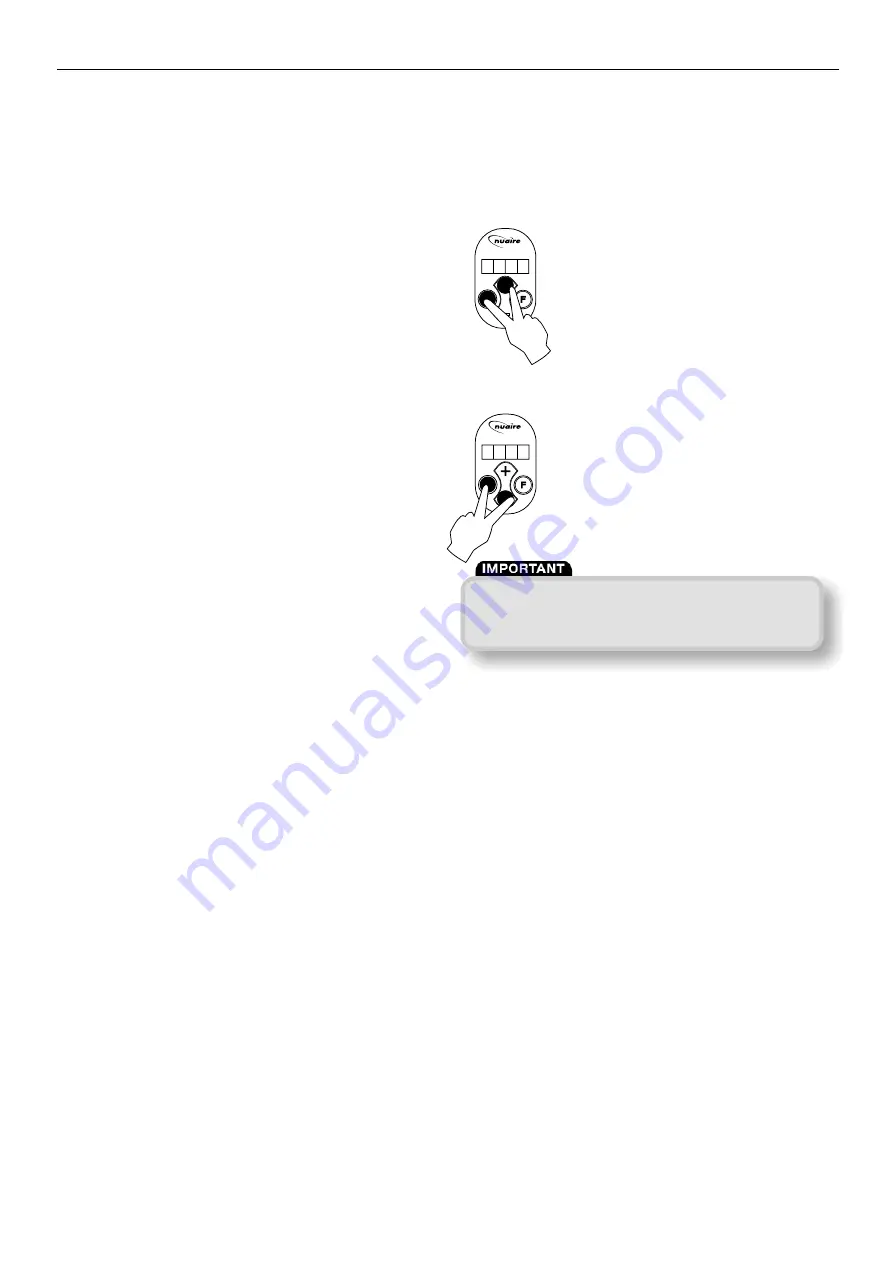
Connect the unit to the mains supply

•  Simultaneously press the keys 

“OK”

and 

“+”

to switch on the unit. 

(only possible after the unit has been switched 

to standby 

“OFF”

displayed).

The first digit on the display indicates the 

position of the 3-way switch.

Switching off

1.

Standby mode; simultaneously press the keys 

“OK”

and 

“-”

to switch off the unit.

The text 

OFF

appears on the display.

2.

Mains power: Isolate the unit from the supply.

Installation and Maintenance

mrXbox90S Mechanical Ventilation with Heat Recovery

-  RESET -

-  ON -

-  SET -

-  OFF -

3.  1  5  0  

When working on the unit, always disconnect from the 

supply by first switching it to standby within the unit and 

subsequently isolating from the mains supply.

-  RESET -

-  ON -

-  SET -

-  OFF -

O  F  F  

Summary of Contents for mrXbox90S

Page 1: ...tem 150 pa at 180 m3 h Filters supplied to be replaced post commissioning Coding mrXbox90S 1 2 Function components 1 Interior temperature sensor measures the temperature of the air from the dwelling 2...

Page 2: ...fact ory def ault settings Speed 1 Speed 2 Speed 3 X Watt age per fan Resist ance Duct Pressure P a 26 Flow R ate m3 h 42 86 Dimensional references 1 spigot to dwelling Supply warmed fresh air 2 spig...

Page 3: ...he right it shows the readout value for instance the preset volume Example The display now shows that the unit is running at ventilation setting 3 at a flow rate of 150 m3 h The four keys have the fol...

Page 4: ...allations current IEE regulations the regulations for connection to interior sewers in dwellings and residential buildings any additional regulations of the local utilities the installation instructio...

Page 5: ...ent fouling and draught Ducting references 1 to dwelling Supply warmed fresh air 2 to outside Exhaust cool stale air 3 from dwelling Extract warm stale air 4 from outside Intake cool fresh air 5 3 Con...

Page 6: ...Combination of a mechanical switch and a radio controlled RC transmitter It s possible to combine 2 RC transmitters with each other It s also possible to combine a mechanical switch with RC transmitt...

Page 7: ...ted with a pressure controlled filter indication and frost control For optimum performance of these features we recommend you initialise the unit This will ensure that the system pressure as function...

Page 8: ...ing 2 U3 setting 3 Settings U4 and U5 do not apply to this unit 3 Press key OK for 1 second to display the selected parameter value 4 The selected parameter value can be changed using keys or 5 The mo...

Page 9: ...cause some settings have an influence on the correct operation of the unit these have been placed in a separate installer parameters set Consequently these parameters can only be modified by the insta...

Page 10: ...s key F 1 second If no key is operated for 5 minutes Press key OK 1 second If no key is operated for 1 minute Press keys F and OK 3 seconds Press key or Press F or key 1 second Press F or key 1 second...

Page 11: ...r data and pressing key takes you back to step no 1 After 5 minutes this menu automatically disappears and the display will show the operational situation again In the event of an error the error code...

Page 12: ...red to modify the settings from operational mode By way of example parameter 8 bypass mode is changed from 1 to 2 1 Press key F for 3 seconds to activate the settings menu 2 Press keys F and OK for 3...

Page 13: ...display the LED on the switch will light up When the filters have been cleaned or replaced press the key OK to reset the filter indication The text FIL will blink for a moment and then the display wil...

Page 14: ...measures the temperature of to the basic pcb the input air is defective The Check the sensor connection to unit operates as normal the wiring Replace the sensor F10 The temperature sensor that Contact...

Page 15: ...th a new filter the filter indication must be reset by pressing key OK The display will blink for a moment to confirm that the filter has been reset The unit will return to operational mode 10 0 Repla...

Page 16: ...ithin the unit is considered Lifting gear such as slings or ropes must be arranged so as not to bear on the casing 3 3 Equipment stored on site prior to installation should be protected from the weath...

Reviews: