


13
30. 06. 20. Document Number 671948
Nuaire |
Western Industrial Estate
|
Caerphilly
|
CF83 1NA
|
nuaire.co.uk
XBC+ with Ecosmart Classic (E) or No (N) Control
Installation Manual
4.0 SETTING TO WORK
Isolation - Before commencing work, make sure that the unit,
switched live and Nuaire control are electrically isolated from the
mains supply.
4.1 Filters
Remove filter access panels (observe and note airflow direction labels),
inspect filters for contamination with construction debris, replace as
necessary. Replace access panels.
Filter pressure drops will depend on actual flow rate and condition.
Observe and record filter pressure drops after performance
commissioning. Typically, filter “dirty” condition occurs when the initial
filter “clean” readings have been increased by 125Pa.
If filter manometers, pressure switches or indicators have been fitted,
they should be set or adjusted to reflect the commissioned system
operation.
4.2 Heating Coils (LPHW)
Observe the Flow and Return connection labels on the unit. Drain and
bleed valves are located on the coil. Other valves may be required in the
system pipe-work depending on the installation (by others).
Where the wet system is at risk of frost damage, the addition of a
proprietary anti-freeze solution to the water is recommended. Any
frost protection offered by the unit’s integral control system will
not operate if the power supply to the unit is interrupted.
Ecosmart frost protection is activated on any Ecosmart unit fitted with
LPHW heating, when the outlet air temperature is 4ºC or below. The
unit reacts by shutting down the fan to prevent a ‘wind chill’ effect
reducing the temperature to a point whereby the coil could freeze
and burst. The unit will also drive open the LPHW valve to a fully open
position to allow full water flow through the coil and the main PCB
will close the ‘Heat demand’ contacts. These contacts could be used to
send a signal to activate the boiler and/or valve to open to provide heat
if not already doing so.
Piped connections should be made to the unit using appropriate
techniques, and all pipework must be independently supported.
No hot work is permitted within one metre of the unit.
Ensure that installed pipework runs do not prevent or restrict access to
the unit at any point.
The completed installation (including the connections within the unit,
as these may be disturbed during installation) shall be pressure tested
to the project engineer’s specification (This is a condition of the unit
warranty).
4.3 Fan Sections
Access to the fan section is via lift off panels (Figures 1 & 23).
For non-Ecosmart units, wiring to the fan motor / unit terminal box
should be mechanically protected and in made in accordance with
the details on the motor name plate and diagram attached to the
unit. With the unit electrically isolated, rotate the fan impeller / drive
manually, checking that it spins freely.
Check all fixings are secure.
Units must not be operated without all access panels in place – damage
to equipment or injury to personnel may result. Units must not be
operated unless control interlocks are in place – damage to equipment
may result.
Test run motor for condition and correct rotation. Check that the
correct current overloads are fitted and that the current being drawn
does not exceed the motor nameplate value. Excessive current
normally indicates that the ductwork system resistance is different to
design.
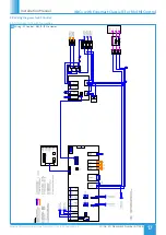
5.0 ELECTRICAL INSTALLATION
The electrical wiring must be carried out by competent persons, in
accordance with good industry practice and should conform to all
governing and statutory bodies i.e. IEE, CIBSE, COHSE etc.
5.1 Connections
5.1.1 Control Connections
Net
- the 4 IDC plug-in connectors are provided for the connection of
compatible sensors, manual controls and for linking the fans together
under a common control. If more than 4 connections are required,
the junction box (product code ES-JB) should be used (see data cable
installation).
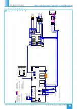
Switch Live (SL) Terminal
- A signal of 100-230V AC will activate the
fan (required at each control).
Note that a signal from an isolating transformer will produce an
unpredictable result and is not recommended.
5.1.2 Damper Connections
OP
- 230V 50Hz 1A max supply to open the damper
CL
- 230V 50Hz 1A max supply to close the damper
N
- Neutral supply to damper
RET
- 230V AC return signal from the damper limit switch indicates the
damper has reached its operating position. If the return signal is not
present, the fan will wait for 1 minute before starting.
Note: If a damper is not fitted, connect a link wire from OP to RET.
This will cancel the delay.
Where units are supplied in modular sections, it will be necessary to
install and connect mains wiring between controls and devices such
as motorised dampers, it may also be necessary to install and connect
mains wiring between sensors and actuators.
Depending on final damper location, extension of the cable looms may
be required.
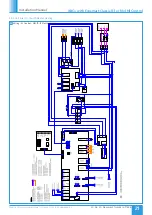
5.1.3 Volt Free Relay Contacts
Note that the volt free contacts are not fused. If these are used to
power any external equipment, the installer must provide adequate
fusing or other protections.
Volt free relay contacts are rated at 5A resistive, 0.5A inductive.
Run Connections
- Contacts closed when the fan is running
Fault Connections
- No Fault = Contacts are closed
Fault
- Contacts are opened
Heat Demand
- Contacts closed when heating is selected.
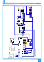
5.1.4 Data Cable Connection
A 4-core SELV data cable is used to connect devices.
Do not run data cable in the same conduit as the mains cables and
ensure there is a 50mm separation between the data cable and other
cables. The maximum cable run between any two devices is 300m
when it is installed in accordance with the instructions.
Please note that the total data cable length used in any system
must be less than 1000m. Keep the number of cable joints to a
minimum to ensure the best data transmission efficiency between
devices.
5.1.5 Maximum Number of Devices
The maximum number of devices (including fans) that can be
connected together via the cable is 32, irrespective of their functions.
5.1.6 Other Low Voltage Cables
Follow the basic principle (as d). Keep the cable run as short as possible,
less than 50 metres. Use screened cable if cable length is more than
2m.


