


15
30. 06. 20. Document Number 671948
Nuaire |
Western Industrial Estate
|
Caerphilly
|
CF83 1NA
|
nuaire.co.uk
XBC+ with Ecosmart Classic (E) or No (N) Control
Installation Manual
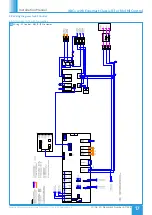
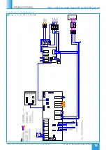
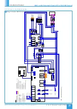
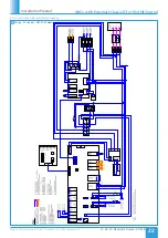
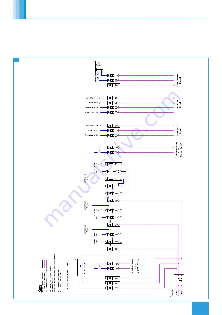
5.8 Wiring Diagrams for BC Control
The wiring illustrations below are for the fans, bypass damper and
electric heater for units without control. All wiring is terminated in
junction boxes fitted to the specified side of the unit.
Notes:
•
Do not wire the power supply to motor via the motor alarm relay
as terminals are only closed after the motor is energized.
•
Any heating/cooling coils fitted are supplied without control valve
and actuator.
•
The alarm relay on condensate may require the use of a contactor
if the host equipment supply is switched.
5.8.1 Unit Sizes 10-15
26
Wiring - BC Control - XBC10-15


