5
30. 06. 20. Document Number 671948
Nuaire |
Western Industrial Estate
|
Caerphilly
|
CF83 1NA
|
nuaire.co.uk
XBC+ with Ecosmart Classic (E) or No (N) Control
Installation Manual
3.4 Condensate Pump
3.4.1 Condensate Pump Alarm
The condensate pump incorporates an alarm function. If the water
level in the condensate tray exceeds a maximum level (for example, as
a result of the discharge tube becoming blocked or frozen), the alarm
contact will open. This contact is internally connected to the heat
exchanger bypass actuator, and the unit will automatically be placed
into bypass mode, preventing further condensate production. Unit
operation will otherwise be unaffected.
3.4.2 Condensate Pump Specification
Maximum flow rate = 12 l/h
Maximum head = 20m Vertical, 100m Horizontal
Pipe Connection size (Condensate) XBOXER XBC = 8 mm
LPHW Coils, if fitted, are tested during manufacture to 16 Bar (using
dry compressed air). Coil and valve assemblies are similarly tested to 10
Bar. The operation of standard equipment is rated to PN6.
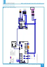
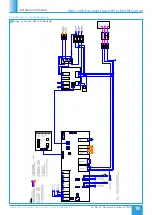
Electrical connections to the unit shall be made in accordance with
the appropriate product and installation wiring diagrams provided, and
shall use appropriately sized and rated cables.
Only the prepared apertures in the unit casing may be used for cable
entry. Do not drill or cut the unit casing for this purpose. Cable access
points are provided at the ends of the control enclosure.
If the control is rotated to aid connection of cables, please ensure that
sufficient flexibility is provided in the final connection run.
To avoid conflict with the unit access panels, it is recommended
that electrical and plumbing service connections to the unit are run
at 90 degrees to the main air flow axis.
Control circuit connections must be segregated (i.e. routed separately)
by a minimum of 50mm from power connections.
The unit rating label shows the maximum electrical load of the
equipment. Connections to the unit may include single phase supply
connections, and a variety of control circuits.
Only the prepared apertures in the unit casing may be used for cable
entry. Do not drill or cut the unit casing for this purpose.
The equipment must be earthed and earth-bonded. Means of local
isolation for maintenance purposes are generally required (by others).
Ensure that all mains connections are isolated.
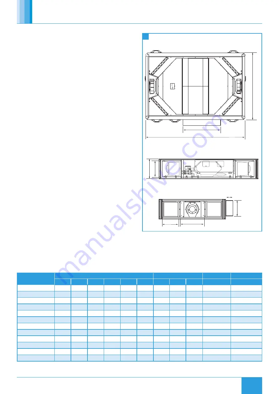
Plan view
Side view
End view
K
M
J
E
F
G
A
B
C
Plan view
Side view
End view
K
M
J
E
F
G
A
B
C
9
Unit Dimensions & Weights
3.5 Dimensions & Weights
†
2 attenuator flange connections are attached to every unit. Add 60mm to dimension 'A' to include both flanges for standard (no roof)
units.
Unit Code
Unit Dimensions (mm)
Control Dimensions (mm)
Unit Weights
Packed Weights
A
†
B
C
J
K
M
E
F
G
(kg)
(kg)
XBC10HA-***-***
1600
1000
260
238
220
347
130
210
640
195
261
XBC10HA-***-**W
1898
1210
335
238
220
347
210
230
674
217
283
XBC15HA-***-***
1600
1000
260
238
220
347
130
210
640
195
261
XBC15HA-***-**W
1898
1210
335
238
220
347
210
230
674
217
283
XBC25HA-***-***
1713
1160
340
252
302
471
130
210
640
242
308
XBC25HA-***-**W
1984
1390
426
252
302
471
276
287
820
267
333
XBC45HA-***-***
1912
1262
400
270
360
531
130
210
640
298
405
XBC45HA-***-**W
2204
1490
487
270
360
531
276
287
954
328
435
XBC55HA-***-***
1900
1560
470
397
430
587
130
210
640
375
546
XBC55HA-***-**W
2204
1796
571
397
430
587
215
386
1000
410
581
XBC65HA-***-***
1913
1572
620
398
580
588
130
210
640
476
652
XBC65HA-***-**W
2204
1796
725
398
580
588
215
514
1000
514
690


