6
20.
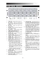
FADER START
– When activated, the
crossfader will send play and cue digital pulse
commands to compatible fader-start devices
connected to the rear panel. To take advantage
of fader start, connect your mixer to a fader-start
compatible device, using standard 1/8” stereo
cables. When you move the crossfader toward
the active channel, the attached device will start.
When it is moved away, the device will cue
(similar to pressing the cue button) or stop,
depending on the device being used.
21.
MASTER FADER
– This control adjusts the
output volume of the Program mix.
22.
STEREO / MONO
– Allows you to output the
Program mix as a mono or stereo signal,
depending on your application. Some amplifier
or speaker systems may require a mono input.
23.
PANNING:
Adjusts the Program mix in the left-
right panorama. As the knob is moved to the
right, the left side of the signal is attenuated and
vice versa.
Note:
This setting affects Master, Record, and
Zone outputs.
24.
METER ASSIGN
– Determines whether PFL or
MASTER audio level is sent to the stereo LED
meter.
25.
STEREO LEVEL INDICATOR
– Quickly and
accurately tracks audio levels. The functionality
of the level indicators is determined by the
METER ASSIGN button.
When using as a MASTER output meter,
set the crossover, equalizer and power amp
inputs to avoid distortion at each step in the
audio chain. Proper attention to the peak
meter results in the punchiest possible sound
without audible distortion.
When used to adjust PFL levels,
PFL cue
signal is sent to the meter through the CUE
ASSIGN buttons. Accurately match channel
levels with the Pre-fader gain and EQ controls
before mixing them together.
26.
ZONE
– Controls the audio level of the Record /
Zone outputs.
Tip:
The Record / Zone outputs can be used to
supply line-level audio to a lighting controller or
sound-activated lighting system.
REAR PANEL OVERVIEW
1
1
1
2
2
2
3
3
3
3
3
3
3
3
4
4
5
6
7
8
9
10
10
11
11
12
13
14
1.
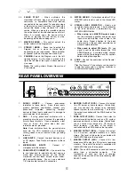
PHONO INPUTS
– Connect phono-level
turntables to these inputs. Since these inputs
provide additional amplification, connect
only
phono-level turntables; connecting line-level
devices to these inputs could result in damage to
your equipment (and your ears).
2.
GND
– If using phono-level turntables with a
grounding wire, be sure to connect the grounding
wire to these terminals. If you experience a low
“hum” or “buzz”, this could mean that your
turntables are not grounded.
Note
: Some turntables have the grounding wire
built into the RCA connection and, therefore,
nothing needs to be connected to the grounding
terminal.
3.
LINE INPUTS
– Connect line-level devices, such
as CD players, Tape Decks or Samplers, to these
inputs.
4.
MICROPHONE INPUTS
– Connect ¼”
microphones to these inputs.
5.
FADER START CONNECTOR
– If you would like
to use fader-start to automatically start and cue
music from external devices via the C3USB
crossfader, connect these outputs to your fader-
start compatible device. You can use a standard
1/8” stereo cable to make this connection.
6.
RECORD OUTPUT (RCA)
– Connect this output
to a CD burner or audio recorder. Alternatively,
you may connect this output to an additional
speaker system for mix monitoring. The level of
this output is controlled with the ZONE knob on the
top panel.
7.
ZONE OUTPUT (RCA)
– Connect this output to
external monitoring device such as a PA system,
powered monitors or a home stereo. Alternatively,
you can connect this output to a CD burner or
audio recorder. The level of this output is
controlled with the ZONE knob on the top panel.
8.
MASTER OUTPUT (RCA)
– Connect this output
to a PA system, powered monitors or a home
stereo. The level of this output is controlled with
the MASTER fader on the top panel.
9.
MASTER OUTPUT (XLR)
– Connect this low-
impedance XLR output to a PA system or powered
monitors. The level of this output is controlled with
the MASTER fader on the top panel.
10.
USB
– These USB connections send and receive
audio from a connected computer. The
functionality of each port (send or receive)
depends on the position of the corresponding USB
SELECT switch.
Summary of Contents for C3USB
Page 2: ......
Page 10: ......
Page 11: ......
Page 12: ...MANUAL VERSION 1 0...
Page 13: ...www numark com...


