Installation
To install the module you will need to mount and wire the board.
Mounting
Inside the can, several two-holed insertion points have been constructed. This allows for either vertical or
horizontal placement of the modules. The insertion points have two sizes of holes, a larger hole and a smaller
hole. The black plastic PCB guides are grooved on one edge where the PC board will be seated. The end with
the half-moon protrusion fits into the larger hole. The smaller hole is for the screw.
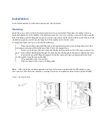
To mount the board, see
Figure 2
and do the following:
1
Place the first black plastic PCB guide in the top insertion point, grooved edge downward. The
half-moon protrusion will be in the large hole. It does not require force.
2
Insert one of the provided screws into the smaller hole (from the inside of the can) to secure it in
place. A screwdriver should reach through the notch that runs the length of the guide to tighten the screw.
3
Position the second PCB guide opposite of the first (grooved edge up) and placed in the lower
insertion point, using the same procedure.
4
Once mounted, screw it in securely.
5
Slide the board in the grooves of both guides.
Note:
Older style enclosures did not provide an exit hole for the antenna included with the GSM module. In such
cases, you must either drill a new hole (5/8 in.) on top of the can or use an optional external antenna (NX-501E-GSM).
Figure 2. Mounting the board


