DSP LASER AP with MCS
LOWER PANEL
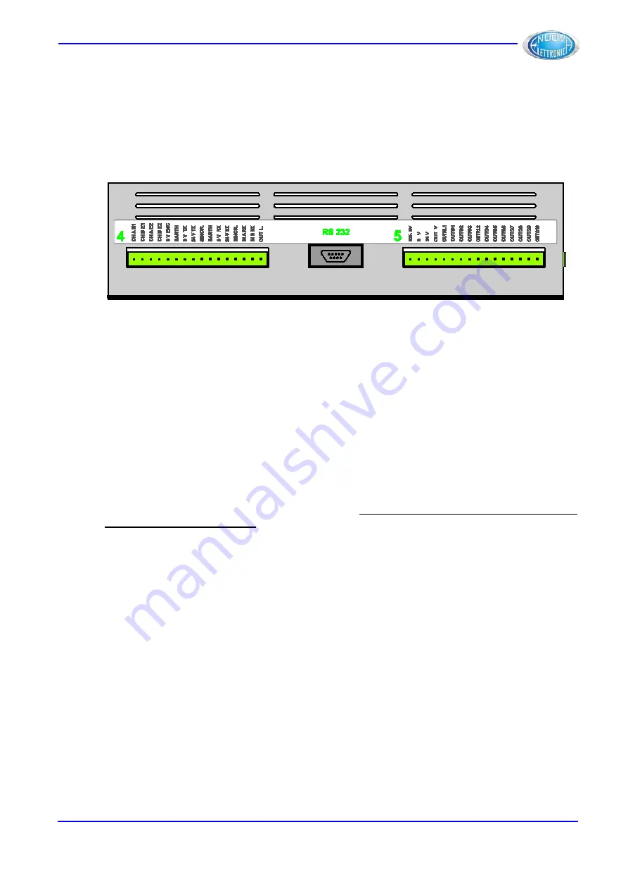
On the face down of MCF module (Figure 17) you can see the type and the numbering of
the inputs and the outputs connected to the relevant connectors and the numbering
assigned to some connectors.
Figure 17
GREEN NUMBERS 4, 5 and label RS 232
Numbers of the male connector, present on the module, which the female connector
marked with the same number must be connected to.
RS 232 is the name of the serial port allowing the communication with CNC or other
dedicated device.
CONNECTOR 4
CH A E1, CH B E1, CH A E2, CH B E2, 0V ENC:
Connections to the inputs of the channels A and B of the encoder 1 connected to the axis
(or hydraulic cylinder) Y1 and connections to the inputs of channels A and B of encoder 2
connected to the axis (or hydraulic cylinder) Y2. 0V ENC indicates the 0V reference of the
channels of the two encoders.
EARTH, 0V TX, 24V TX, SINCR.:
Connections between DSP LASER AP –TX and MCS (see par. 10.4.3).
EARTH, 0V RX, 24V RX, SINCR., IN A RX, IN B RX, OUT L.:
Connections between DSP LASER AP –RX and MCS (see par. 10.4.3).
CONNECTOR 5
RIF 0V:
One of the connections where the reference 0V of MCS power supply is available.
0Vcc, 24Vcc:
One of the two connections to MCS power supply by means of terminals 0Vcc and 24Vcc
(see par. 10.4.2.1).
OUT V:
Output which communicates, rapidly, to CNC that the lowest central sensor (Area A) of DSP
LASER AP has intercepted the sheet. Output state is: ON(24Vcc)=1 or OFF(0Vcc)=0.
DLAM01EN
21
Summary of Contents for DSP LASER AP
Page 2: ......
Page 4: ......
Page 50: ...DSP LASER AP with MCS Figure 34 44 DLAM01EN...


