DSP LASER AP with MCS
OUTRL1, OUTRL2:
Outputs suitable to control the relays to put in emergency the components connected to
their NO contacts (see par. 10.4.2.4). Output state is: ON(24Vcc)=1 or OFF(0Vcc)=0.
OUTG1÷OUTG10:
Generic outputs with capability to deliver up to 0,4A at 24Vcc. The output state
ON(24Vcc)=1 or OFF(0Vcc)=0 is shown on the display (Figure 13).
RIGHT PANEL
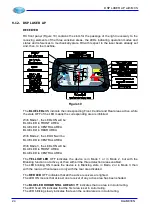
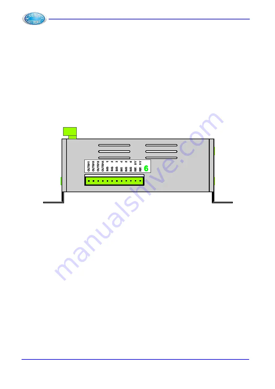
On the right face of MCS module (Figure 18) you can see the type and the numbering of the
inputs and the outputs connected to the relevant connector and the numbering assigned to
the connector.
Figure 18
GREEN NUMBER 6
Number of the male connector, present on the module, which the female connector marked
with the same number must be connected to.
CONNECTOR 6
OUTG11÷OUTG14:
Generic outputs with capability to deliver up to 0,4A at 24Vcc. The output state
ON(24Vcc)=1 or OFF(0Vcc)=0 is shown on the display (Figure 13).
ING1÷ING6:
Generic inputs. The state 1=24Vcc and the state 0=0Vcc are shown on the display (Figure
12).
RIF 0V, RIF 0V :
Two of the connections where the reference 0V of MCS power supply is available.
22
DLAM01EN
Summary of Contents for DSP LASER AP
Page 2: ......
Page 4: ......
Page 50: ...DSP LASER AP with MCS Figure 34 44 DLAM01EN...

