DSP LASER AP with MCS
•
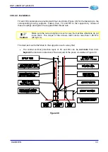
The lower horizontal protection layer of TX and RX is perpendicular to the bending
layer along all the adjustment stroke of the supports, as visible in Figure 31.
Figure 31
•
The lower horizontal protection layer of TX and RX is parallel to the upper table, so
that the value of the safety distance is constant for all the length of the upper tool, as
visible in Figure 32.
Figure 32
10.4. Electric connection
10.4.1. List of signals managed by MCS
The pins (I/O) on the SAFETY CONTROL MODULE, called MCS, are listed in the following
table which describes their function.
The safety outputs, from OUTS1 to OUTS8 and the relevant inputs for the possible monitors
of the controlled devices (OUTS8 is lacking), can be assigned to different operating states
by means of a programming procedure, under password, and using only the display and the
MCS keys.
Information
:
The short circuit on the wiring of the outputs cannot be detected by MCS.
Then, it is necessary to use suitable wiring techniques to avoid it.
This makes very easy, but absolutely safe, the adaptability of MCS to the different hydraulic,
and not only, configurations which control the movement of the moveable part of the press
to manage in safety, according to what required by Standard EN12622 and with a safety
level up to SILCL3 as indicated in Standard EN62061.
These outputs can manage a current of 3,2A at 24Vcc. This makes them suitable to any
type of solenoid valve used in the market of the press brakes.
WRONG
CORRECT
WRONG
WRONG
CORRECT
WRONG
TX
RX
TX
RX
TX
RX
90°
34
DLAM01EN
Summary of Contents for DSP LASER AP
Page 2: ......
Page 4: ......
Page 50: ...DSP LASER AP with MCS Figure 34 44 DLAM01EN...


