DSP LASER AP with MCS
10.4.2.2. Foot Pedal Controls with “antipanic” and Emergency chain
Foot Pedal Controls
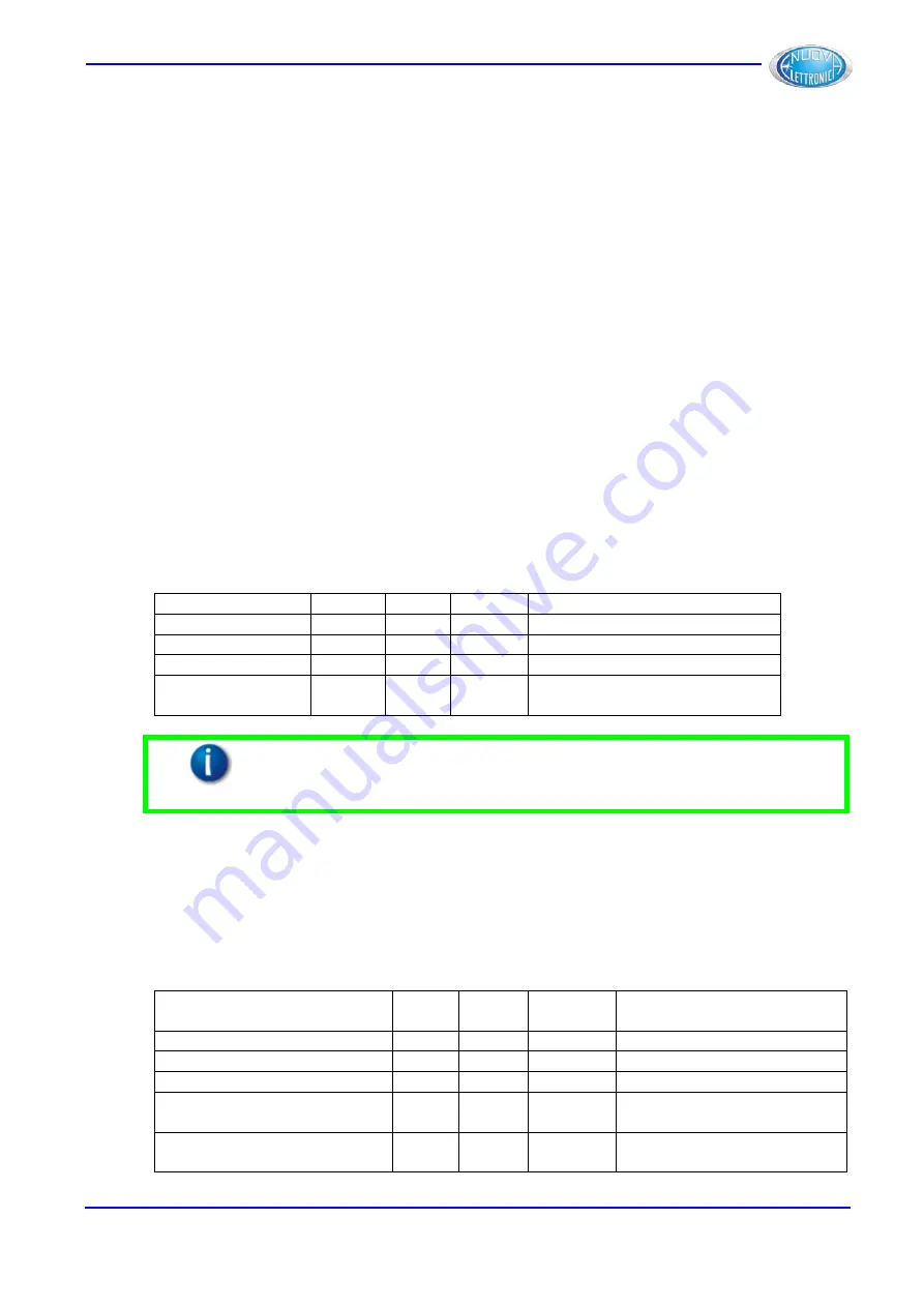
MCS can manage up to 2 foot pedal controls.
In “one foot pedal control” mode, it is not necessary to wire the selector Foot Pedals
Controls (INS 3, 4 and 21) and the Foot Pedal Control 2 (INS 18 and 19). In this case,
assign the value “1P” to the programming parameter B2.
In “two foot pedal controls” mode, through the three-position Selector Foot Pedal Controls,
you can choose if using only Foot Pedal Control 1 (position 1 of selector), only Foot Pedal
Control 2 (position 2 of selector) or both Foot Pedal Controls together (position 3 of
selector).
The two foot pedal controls mode can operate in two different ways, depending on the value
assigned to the programming parameter B2.
•
If the value “2P N” (2 Pedals Normal) has been assigned to B2, the downstroke
request is acquired by MCS when both the pedals are pressed, independently from
the order they are pressed.
•
If the value “2P MS” (2 Pedals Master-Slave) has been assigned to B2, the
downstroke request is acquired by MCS when both the pedals are pressed. In this
case, however, the Slave (Pedal 2) must be pressed before the Master (Pedal 1),
otherwise MCS will signal Error.
Always in “two foot pedal controls” mode, the pressure of one pedal is signalled to the other
station by the blinking of the foot pedal control led. When Pedal 2 is pressed, for example,
the led pedal 1 in the foot pedal control 1 will blink.
Parameter B2
INS 3
INS 4
INS21
Selected Foot Pedal Control
“1P”
X
X
X
Foot Pedal Control 1
“2P N“ o ”2P MS”
24V
0V
0V
Foot Pedal Control 1
“2P N“ o ”2P MS”
0V
24V
0V
Foot Pedal Control 2
“2P N“ o ”2P MS”
0V
0V
24V
Foot Pedal Control 1 +
Foot Pedal Control 2
Information
:
All the configurations of inputs INS3, INS4 and INS21 different from
those reported in this table will cause a Lock of MCS, which will be
restored when these inputs will return in a correct configuration.
The selection of the foot pedal controls can be even demandated to CNC through the use of
the serial connection RS232. To use this functionality, it is necessary to assign the value
“2P N CNC” to the parameter B2 for the Normal mode, or the value “2P MS CNC” for the
Master-Slave mode. In this case, it is necessary to connect INS3, INS4 to 24Vcc by means
of a NO/NC selector. When the selector is in default position 1 (INS3 = 24V, INS4 = 0V),
only Foot Pedal Control 1 is active; when the selector is in default position 2 (INS3 = 0V,
INS4 = 24V), the selection is executed by CNC via RS232.
Parameter B2
INS 3
INS 4
RS232
Selected Foot Pedal
Control
“2P N CNC“ o ”2P MS CNC”
24V
0V
X
Foot Pedal Control 1
“2P N CNC“ o ”2P MS CNC”
0V
24V
Ped1
Foot Pedal Control 1
“2P N CNC“ o ”2P MS CNC”
0V
24V
Ped2
Foot Pedal Control 2
“2P N CNC“ o ”2P MS CNC”
0V
24V
Ped1+
Ped2
Foot Pedal Control 1+
Foot Pedal Control 2
“2P N CNC“ o ”2P MS CNC”
0V
24V
X
Foot Pedal Control 1 +
Foot Pedal Control 2
DLAM01EN
41
Summary of Contents for DSP LASER AP
Page 2: ......
Page 4: ......
Page 50: ...DSP LASER AP with MCS Figure 34 44 DLAM01EN...

