DSP LASER AP with MCS
11.4. First installation of TX and RX
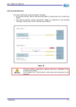
For the first installation, it is necessary to optically align the devices DSP LASER AP TX and
RX to the upper tool of the machine and between them. For this purpose, the test and
positioning tool is supplied with DSP LASER AP (Figure 52).
The horizontal protection layer must be placed at tool tip at a safety distance equal to the
maximum stop distance allowed by DSP LASER AP + 5mm. The maximum allowed values
are, as described below, three: 14mm, 18mm and 24mm. To set the system in one of the
three positions, it is necessary to align the laser beam in area 1 for a maximum SA of 14
mm, in area 2 for a maximum SA of 18 mm, in area 3 for a maximum SA of 24 mm. In the
description below, the positioning in area 1 is described. To execute the positioning in the
other areas, the procedure is the same, obviously only the area changes.
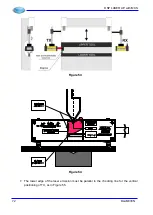
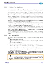
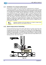
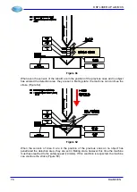
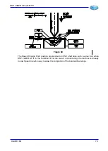
Figure 52
The first adjustment to execute is to position the laser beam in parallel to the tip of the upper
tool for all its length. To do this, act as follows:
1.
Set a reduced closing speed, lower than or equal to 10 mm/sec.
2.
Lay the test and positioning instrument over the lower tool in the position “point A”
near TX (Figure 53).
3.
Lower the upper tool until bringing its tip near the vertex of the groove of the notch
present in the upper part of the tool (Figure 54).
4.
Adjust the TX height moving vertically the support (arrow 1 in Figure 53), in such a
way that the LOWER EDGE OF THE LASER EMISSION coincides with the upper line
of grey area 1, 2 or 3. In the example it is the line 1 of the Test and positioning
instrument (Figure 54).
5.
Then adjust TX along all the transversal axis of the bend axis (arrow 2 in Figure 53),
in such a way that the lateral edges of the laser emission are simmetrically contained
within the two surfaces defined by the two vertical lines and marked with R and F
(Figure 54).
6.
Fasten TX, without tightening, in this position.
DLAM01EN
71
Summary of Contents for DSP LASER AP
Page 2: ......
Page 4: ......
Page 50: ...DSP LASER AP with MCS Figure 34 44 DLAM01EN...

