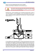
DSP LASER AP with MCS
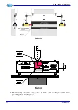
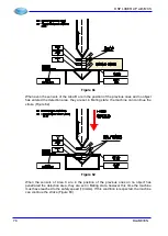
Figure 55
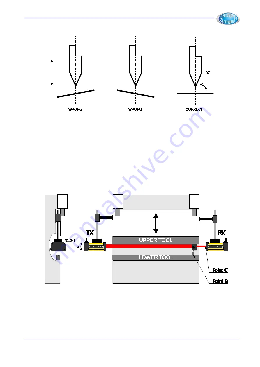
8. Then move the test and positioniong instrument on the lower tool to position “
point B
”
(Figure 56) or, however, near RX.
9. Verify that the laser beam is yet in the previous position (Figure 54). If the beam is in a
different position (very likely situation), adjust TX in accurate way in direction of arrows 3
and 4, without intervening on the calibration executed previously (movements indicated by
arrows 1 and 2 of Figure 53).
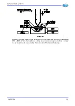
Figure 56
10. The lower edge of the laser emission must be parallel to the upper table (Figure 57), so
that the value of the safety distance can be constant for all the length of the upper tool.
DLAM01EN
73
Summary of Contents for DSP LASER AP
Page 2: ......
Page 4: ......
Page 50: ...DSP LASER AP with MCS Figure 34 44 DLAM01EN...


