DSP LASER AP with MCS
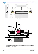
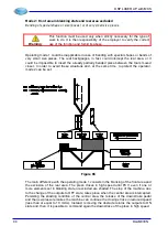
Figure 57
11. After having executed the calibration with the test instrument in position “
point B
”, move it
to position “
point A
” and verify that the laser emission is positioned as in Figure 50.
Tighten the fixing screws of TX to moving support.
12. Move the instrument test in position “
point B
” and observe the front side of RX, “
point C
”
which is lighted by a part of leaser beam coming out from the SLOT FOR THE
HORIZONTAL AND VERTICAL POSITIONING of RX.
Figure 58
13. Move horizontally RX in such a way that the rectangular light is between the RX
HORIZONTAL POSITIONING REFERENCES (Figure 58).
14. Move vertically RX in such a way that the circular light is within one of the RX VERTICAL
POSITIONING REFERENCES. The reference must be the one with the same number of
the line where has been positioned the LOWER EDGE OF THE LASER EMISSION (in this
example, within reference 1, Figure 54).
15. Remove the test instrument from the machine.
16. Verify that the GREEN LED becomes ON, as confirmation of the alignment occurred.
17. If not, act on the RX parallelism adjustments, as in point 5 you have done for TX, so
making the GREEN LED becomes ON.
18. Tighten the RX fixing screws to the moving support.
The correct installation of the supports and the mechanical adjustment of the device foresee
that, at each tool change, the heights of the supports is simply adjusted as function of the
punch height, without any intervention by the user on the horizontal adjustment and on the
parallelism.
74
DLAM01EN
Summary of Contents for DSP LASER AP
Page 2: ......
Page 4: ......
Page 50: ...DSP LASER AP with MCS Figure 34 44 DLAM01EN...

