DSP LASER AP with MCS
11.5. Verification of the stop distance
At switch-on, before entering in operating modality, MCS must carry out the verification of
the machine stop distance.
This verification consists in making the machine moving part covers a given space (value of
parameter A5) to reach the maximum speed. The system commands to stop the
downstroke and, when the machine is securely stopped, the detection of the space covered
by the machine by inertia, that is the stop distance, is measured.
If this distance is less than or equal to that allowed (parameter A2), MCS switches to
operating modality. Otherwise, it is necessary to repeat the verification of the stop distance.
In this case, decreasing the machine downstroke speed, the stop distance can be reduced
and, then, pass the test.
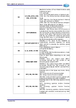
When you switch the device on, the led of the button Sheet Edge is OFF. Once have
verified that all the peripheral units are in the correct state (side door closed, etc.) and have
reset all the active emergencies, the led starts blinking rapidly.
At this point, to execute the test of the stop distance, move the press to PMS and command
a downstroke in High Speed. MCS, after the machine has covered a distance equal to that
set in parameter A5, command the stop and measures the space covered by the press
recording even the detected value of High Speed (see chap.11.7).
If the measured distance is less than or equal to that set in parameter A2, then the led of
the Sheet Edge will change to fixed ON (test of stop distance successful), otherwise it will
continue blinking and the test shall be repeated.
Before executing the test of the stop distance, it is however possible to execute a machine
dowstroke in low speed for maintenance operations.
The Stop Distance of the machine must be verified at least every 30 hours. MCS, passed
30 hours of continue operation, will automatically start the function of Verification of the Stop
Distance.
11.6. Sheet Edge Acquisition
The acquistion of the sheet edge by the device is necessary in each one of the following
cases:
•
Start of working in operating mode
•
Tool change involving a new adjustment of the receiviong device (DSP LASER AP
RX)
•
Change of the sheet thickness.
To do this, execute the following procedure:
•
Move the press upward and make sure the laser beam is free from obstacle.
•
Press the Sheet Edge button: the led of the button Sheet Edge changes from OFF to
fixed ON. In this way, the function for the calculation of the sheet edge is active.
•
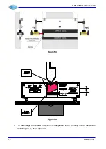
Move the press downward until the lower central sensor of DSP AP RX touches the
sheet. MCS, as soon as detects the sheet edge, commands a stop and the led of the
button Sheet Edge goes OFF.
Important: during this operation, the laser must not be shaded by anything, except from the
sheet. Therefore, remove all that could obstacle the execution of this function. The minimum
sheet thickness readable by DSP LASER AP RX is 0.6mm.
Residual
risk
:
In case of sheet with thickness lower than 0.6 mm and wrong setting of
PCV, you could have a shock in high speed of the crossbeam against the
sheet with an unexpected movement of this.
DLAM01EN
75
Summary of Contents for DSP LASER AP
Page 2: ......
Page 4: ......
Page 50: ...DSP LASER AP with MCS Figure 34 44 DLAM01EN...

