DSP LASER AP with MCS
15.
Removal and reinstallation after the repair
If DSP LASER AP presents a defect or a malfunction, and then it is necessary to disconnect
from the machine to send it to repair, execute the following procedure. This procedure
allows avoiding the cable disconnection, limiting the operation only to the disassembly of
the device component to repair.
•
Disconnect MCS from the mains: the whole device, TX and RX included, will be
automatically disconnected from power supply.
•
Extract the female connectors from the relevant male connectors of MCS.
•
Disconnect mechanically MCS unscrewing the four screws which anchor it to he
electric panel.
•
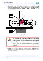
Remove the rear cover from TX and RX unscrewing the four screws (Figure 75).
•
Extract the 4-pole female connector from the male one on TX
•
Extract the 8-pole connector on RX.
•
Extract even the Faston female connector from the male connector anchored on the
RX container.
•
Disconnect mechanically TX and RX from the machine.
Figure 75
•
Send the three parts to Manufacturer, according to modalities described in the chapter
Warranty, indicating the observed defect.
•
Before reconnecting the parts returned from the repair, make sure the machine is
disconnected from mains.
•
Reconnect mechanically TX and RX to their moving supports and reconnect
mechanically MCS to the electric panel
•
Insert gently the female connectors of TX, RX and MCS into the relevant male
connectors.
•
Put the rear cover of TX and RX to its place and screws the four screws.
•
Execute again the commissioning and the test procedures described in the relevant
chapter.
DLAM01EN
99
Summary of Contents for DSP LASER AP
Page 2: ......
Page 4: ......
Page 50: ...DSP LASER AP with MCS Figure 34 44 DLAM01EN...


