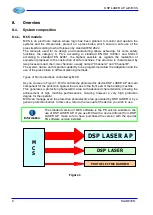
DSP LASER AP with MCS
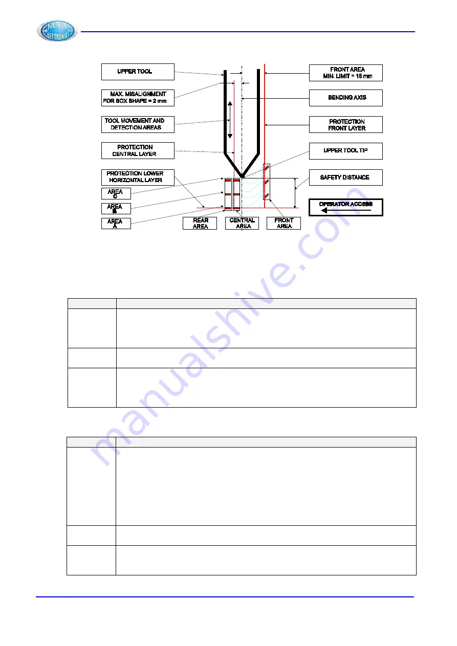
Figure 8
As regards the Blanking function used for bending boxes, the detection area is subdivided
in 3 different areas: a
front area
(towards the operator), a
central area
(under the tip of the
upper tool and sligthly shifted towards the rear part of the press) and a
rear area
(towards
the rear part of the press brake).
Area
Task
Front
Protects the operator’s fingers too close to the working area. Moreover, it
protects against the risk of squashing between the die edge and the tip of the
upper tool.
This area can be inhibited for special machining.
Central
Protects the operator against the squashing between the tip of the upper tool
and the sheet/die.
Rear
Avoid the squashing between the tip of the upper tool and the rear
backgauges.
This area can be inhibited for special machining or if the rear
backgauges are intercepted.
As regards the Automuting function, the detection areas are 3: Area A, Area B and Area C.
Area
Task
Area A
Area A is composed by the 3 lowest sensors: one front sensor, one central
sensor and one rear sensor. The set of sensors of the Area A is that
intercepting first an obstacle during the downstroke. The detection of the sheet
thickness is executed by the central sensor of the Area A.
Note. If the machine Stop Distance, measured by MCS during the test, is less
than 6mm, the Area A is automatically disabled by DSP LASER AP during the
normal operation. It remains, however, active during the verification of the Stop
Distance and the Sheet Edge Acquisition
.
Area B
Area B is composed by the 3 sensors located above the Area A: one front
sensor, one central sensor and one rear sensor.
Area C
Area C is composed by the 3 sensors located above the Area B: one front
sensor, one central sensor and one rear sensor. This set of sensors is the
closest to the tool tip.
14
DLAM01EN
Summary of Contents for DSP LASER AP
Page 2: ......
Page 4: ......
Page 50: ...DSP LASER AP with MCS Figure 34 44 DLAM01EN...


