DSP LASER AP with MCS
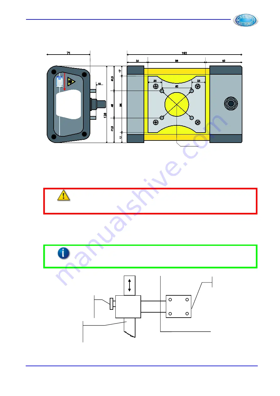
Figure 28 indicates the dimensions of TX and RX, which are identical.
Figure 28
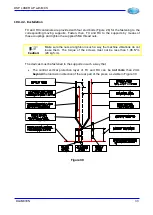
The moving supports must be firmly fastened to the upper tool-holder table, for example by
means of plates provided with extensions for the moving supports of TX and RX (Figure
29).
Warning
:
The plates must be installed behind the upper table or on its sides. The
front installation is discouraged, because the plates could create areas of
mechanical danger due to the movement of the table and to the possible
contact of the sheet against the table during the work.
The fastening must be made in such a way that:
•
Plates are made of rigid and indeformable material (e.g.: steel)
Information
:
The stiffness of the mechanical system must be such that the setting
must resist under the application of a force of, at least, 250 N along the
support axes.
Figure 29
Upper table
Lock/unlock
device
Moving
support
Plate
DLAM01EN
31
Summary of Contents for DSP LASER AP
Page 2: ......
Page 4: ......
Page 50: ...DSP LASER AP with MCS Figure 34 44 DLAM01EN...


