3
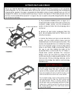
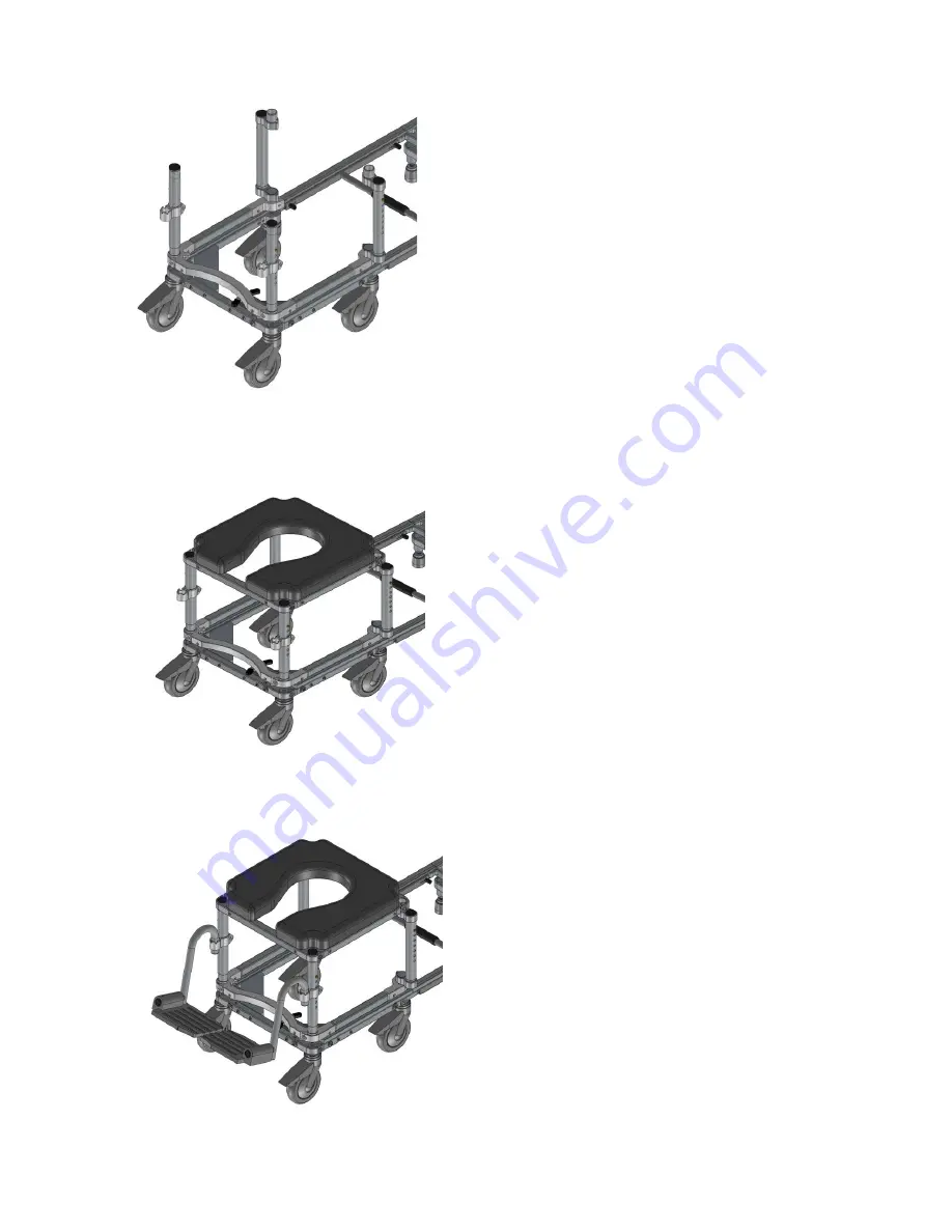
FIGURE 4
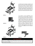
FIGURE 5
FIGURE 6
D. Install the legs into the shuttle frame by sliding
the leg ends into the 1” diameter holes on the
shuttle frame corners and positioned per Figure 4.
Again, make sure that the legs go all the way in
and then tighten the “pinch-clamp” corners with
the ¼” Yellow T-Handle Allen wrench.
E. Install the seat frame by lining up the leg holes
at the bottom of the (4) corners of the seat frame
with the legs per Figure 5. Slide the seat frame
down onto the legs until they “bottom-out”. Once
the legs have bottomed out and are securely
fitted into the holes. Tighten the associated
“pinch-clamp” corners with the ¼” Yellow T-
Handle Allen wrench.
F. Place the footrests in footrest clamps per Figure
6. The footrests are height adjustable by
positioning the footrest clamps along the front
legs and again, using the ¼” Yellow T-Handle Allen
wrench, tighten in the desired positions.


